Bosch DVR4C1081 Installation Manual - Page 8
Installation - dvr
 |
View all Bosch DVR4C1081 manuals
Add to My Manuals
Save this manual to your list of manuals |
Page 8 highlights
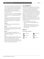
DVR4C | Installation Manual | Installation EN | 8 2 Installation To install the DVR make the connections described below and then enter the relevant data in the quick install menu. 2.1 Connections Primary connections 1. Connect the cameras to the BNC camera input connectors. (Set impedence to Hi-Z only when the video loop-through outputs are used.) > The DVR4C automatically configures itself as a PAL or NTSC unit by detecting the signal format of the first connected camera (lowest camera input number). 2. Connect a monitor to the BNC output MON Out. > Connect the unit to the monitor using 75-ohm video coaxial cables with BNC connectors. 6. Connect up to four alarm output relays via the terminal connector. > Relay 1 responds to an input alarm, Relay 2 responds to a system failure and the other relays are assigned to the remote software. Configure the alarm outputs as N/O or N/C in the menu system. 7. Connect to your network via the Ethernet port. > The DVR4C is delivered with the DHCP function switched on, so IP addresses are assigned automatically if the network server uses DHCP. (Refer to the System settings/Connectivity/Network setup menu.) 8. Use the RS232 connector to connect to a PSTN line. > The serial RS232 console port connector is used to connect a PSTN modem or a text device to the unit. Use a null-modem cable to connect the serial port of the external equipment to the unit. The Baud rate can be selected in the menu system. Optional connections 3. Connect up to four audio inputs via the RCA connectors. 4. Connect an audio output device via the RCA connector. 5. Connect up to four (alarm) inputs via the terminal connector. > Each input line can be switched by a relay contact from devices such as pressure pads, passive infra-red detectors, smoke detectors and similar devices. You can configure the alarm inputs as N/O or N/C in the menu system. The default is N/O. Powering up 9. Switch on all connected equipment. 10. Connect the power cord to the unit and switch on. Power switch Audio inputs Camera inputs RS232 connector Alarm input Relay output Audio output 100-240 Vac Bosch Security Systems | Version 1.1 Monitor output PC Network connector LAN / WAN
-
 1
1 -
2
-
 3
3 -
 4
4 -
 5
5 -
 6
6 -
 7
7 -
 8
8 -
 9
9 -
 10
10 -
 11
11 -
 12
12 -
 13
13 -
14
-
15
-
16
-
17
-
18
-
19
-
20
-
21
-
22
-
23
-
24
-
25
-
26
 |
 |
