Bosch NGM5024UC Use & Care Manual (all languages) - Page 11
Control Knobs
 |
UPC - 825225858355
View all Bosch NGM5024UC manuals
Add to My Manuals
Save this manual to your list of manuals |
Page 11 highlights
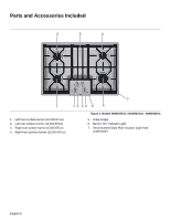
CAUTION: To avoid possible injury or damage to the appliance, ensure grates are installed exactly per installation instructions and not backwards or upside down. Four-burner models: When placing center grate, make sure the horizontal bar aligns with the horizontal, center bar of the left and right grates. See figure, "Four-Burner Center Grate Placement" below. Control Knobs The cooktop has one control knob for each burner. Push down and turn to the left to light and set the desired heat setting. CAUTION: Failure to operate knobs properly may result in personal injury and damage to the appliance. The cooktop has standard burner controls and rubber grommets. Align Horizontal Bars Figure 7: Four-Burner Center Grate Placement Five-burner models: When placing center grate, make sure the horizontal rectangular support is located at the front of the cooktop. See figure, "Five-Burner, Center Grate Placement" below. Figure 9: Standard Burner Control Knob The standard burner controls have an infinite number of heat settings. To operate: Select the appropriate control knob, push down and turn counterclockwise to the desired flame size. Turn off by turning the control knob clockwise to OFF. Burner Control Knob Removal To remove knob and grommet: With burner in the OFF position, gently lift knob up and off. Gently pull the grommet from the sides and lift out. Rectangular Support Figure 8: Five-Burner, Center Grate Placement WARNING: To avoid possible electric shock, do not reach through control opening into rough-in box. To replace grommet and knob: Carefully insert the grommet into the opening, ensuring that the maintop is seated in the track around the entire perimeter of the grommet. Replace control knob by placing indicator line at the 12 o'clock position. Press down firmly. English 9
-
 1
1 -
2
-
3
-
4
-
5
-
 6
6 -
 7
7 -
 8
8 -
 9
9 -
 10
10 -
 11
11 -
 12
12 -
 13
13 -
 14
14 -
 15
15 -
 16
16 -
17
-
18
-
19
-
20
-
21
-
22
-
23
-
24
-
25
-
26
-
27
-
28
-
29
-
30
-
31
-
32
-
33
-
34
-
35
-
36
-
37
-
38
-
39
-
40
-
41
-
42
-
43
-
44
-
45
-
46
-
47
-
48
-
49
-
50
-
51
-
52
-
53
-
54
-
55
-
56
-
57
-
58
-
59
-
60
-
61
-
62
-
63
-
64
 |
 |
