Bosch NGM5024UC Installation Instructions - Page 8
Connect Electrical Supply, Burner Cap Placement
 |
UPC - 825225858355
View all Bosch NGM5024UC manuals
Add to My Manuals
Save this manual to your list of manuals |
Page 8 highlights
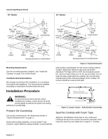
off valve and pressure regulator. Always use a new flex line. Rough-in Box Pressure Flex Gas Line Regulator Shows Direction of Gas Flow Gas Shut-Off Valve Cabinet Floor Gas Stubout 1/2" Female Pipe Threads Supply Cord 120 V CL of Wall Receptacle Connect Electrical Supply Before connecting 5-foot (1.5 m) supply cord to wall receptacle, make certain that gas shutoff valve and all burner controls are in OFF position. Burner Cap Placement WARNING: To prevent flare-ups, do not use the cooktop without all burner caps and all burner grates properly positioned. Figure 8: Gas and Electrical Location Check supply line connections for leaks using a soap solution. Do not use a flame of any sort. 1. Turn on gas. 2. Apply a non-corrosive leak detection fluid to all joints and fittings in the gas connection between the shut-off valve and the range. Include gas fittings and joints in the range if connections may have been disturbed during installation. Bubbles appearing around fittings and connections indicate a leak. 3. If a leak appears, turn off supply line gas shut-off valve and tighten connections. 4. Retest for leaks by turning on the supply line gas shutoff valve. When leak check is complete (no bubbles appear), test is complete. 5. Wipe off all detection fluid residue. Important Notes for Gas Connection: • The appliance and its individual gas shutoff valve must be disconnected from the gas supply piping system during any pressure testing of that system at test pressures in excess of 1/2 psig (3.5kPa). • The appliance must be isolated from the gas supply piping system by closing its individual manual shut-off valve during any pressure testing of the gas supply piping system at test pressures equal to or less than 1/ 2 psi (3.5kPa). WARNING: To prevent burns, do not touch burner caps or grates while hot. Turn the cooktop off and allow the burners to cool. The burner caps must be properly placed for the cooktop to function properly. If the burner cap is not properly placed, one or more of the following problems may occur: • Burner flames are too high. • Flames shoot out of burners. • Burners do not ignite. • Burner flames light unevenly. • Burner emits gas odor. Placing Burner Caps Each cap has a letter (A, D, or F) cast in the underside of the cap that corresponds to a letter (A, D, or F) cast in the burner base that is attached to the appliance. • After electrical connection is complete, place each burner cap on its correct burner base per its corresponding letter designation. See figure "Burners Caps" on page 7. • Place burner cap gently on top of base so that the prongs of the burner base fit snugly into the groove of the burner cap. English 6
-
 1
1 -
2
-
 3
3 -
 4
4 -
 5
5 -
 6
6 -
 7
7 -
 8
8 -
 9
9 -
 10
10 -
 11
11 -
 12
12 -
 13
13 -
14
-
15
-
16
-
17
-
18
-
19
-
20
-
21
-
22
-
23
-
24
-
25
-
26
-
27
-
28
-
29
-
30
-
31
-
32
 |
 |
