Bose Lifestyle 5 The Bose® Lifestyle® amplifier - Owner's gu - Page 16
Connecting speakers to your Lifestyle® stereo amplifier, Connecting speakers to your Lifestyle - remote
 |
View all Bose Lifestyle 5 manuals
Add to My Manuals
Save this manual to your list of manuals |
Page 16 highlights
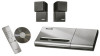
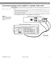
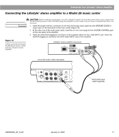
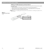
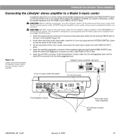
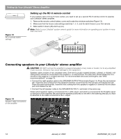
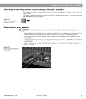
Setting Up Your Lifestyle® Stereo Amplifier ® Figure 13 RC-5 remote switch settings Setting up the RC-5 remote control If your system uses a Model 5 music center, you need to set up a second RC-5 remote control to operate your Lifestyle® stereo amplifier. 1. Remove the remote control battery cover and locate the miniature switches (Figure 13). 2. Make sure that the house code settings (switches 1, 2, 3, and 4) match those in your first remote. 3. Slide switch 5 down (off) and 6 up (on). Note: Refer to your Lifestyle® system owner's guide for more information on operating your system in more than one room. ON K40 l 2345678 Connecting speakers to your Lifestyle® stereo amplifier CAUTION: DO NOT connect the amplifier to powered speakers of any make or model, nor to any amplified music sources. Doing so may cause damage to the equipment. Speaker cable consists of two insulated wires. One wire is usually marked (striped, collared, or ribbed), indicating that it should be connected to the positive (+ or red) terminal. The plain wire should always be connected to the negative (- or black) terminal. For recommended wire sizes and lengths, see "Wire recommendations" on page 18. • Connect the right speaker cable to the SPEAKER OUTPUT R terminals (Figure 14). Press the red terminal tab. Insert the wire coming from the speaker's positive (+) terminal into the red jack and release the tab. Press the black terminal tab. Insert the wire coming from the speaker's negative (-) terminal into the black jack and release the tab. • Connect the left speaker cable to the SPEAKER OUTPUT L terminals in the same way. Notice which speaker cable is connected to the L (left) output, and which is connected to the R (right) output on the back of the amplifier. Be sure that the speaker positioned on the left in the listening area (as you face it) attaches to the cable connected to the L output. Figure 14 Speaker cable connections on the amplifier 14 January 4, 2002 AM262840_00_V.pdf
-
 1
1 -
2
-
3
-
4
-
5
-
6
-
7
-
8
-
9
-
10
-
 11
11 -
 12
12 -
 13
13 -
 14
14 -
 15
15 -
 16
16 -
 17
17 -
 18
18 -
 19
19 -
 20
20 -
 21
21 -
22
 |
 |