Bose Lifestyle T20 SL2 wireless surround link - Owner's guide - Page 6
Making the connections - back
 |
View all Bose Lifestyle T20 manuals
Add to My Manuals
Save this manual to your list of manuals |
Page 6 highlights
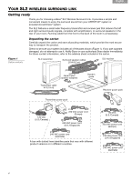
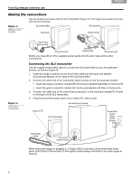
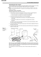
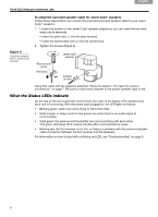
Svenska Nederlands Italiano Français Español Deutsch Dansk English YOUR SL2 WIRELESS SURROUND LINK Making the connections Use the small power pack with the SL2 transmitter (Figure 3). The large power pack is for use with the SL2 receiver. Figure 3 Different power supplies SL2 transmitter Input jack SL2 receiver Output jacks Figure 4 Transmitter connections Transmitter power pack AC power jack Receiver power pack AC power jack Before you plug either of the supplied power packs into the wall, make all the other connections. Connecting the SL2 transmitter Use the supplied transmitter cable to connect the SL2 transmitter to your Acoustimass® module, as follows (Figure 4): 1. Insert the single connector at one end of the cable into the input jack labeled Acoustimass Module on the back of the SL2 transmitter. 2. Connect the other end of the transmitter cable to jacks on the Acoustimass module. • Insert the purple connector marked RR into the jack labeled Right Rear or Surround R. • Insert the green connector marked LR into the jack labeled Left Rear or Surround L. 3. Connect the cable end of the transmitter power pack to the small jack labeled DC Power on the back of the SL2 transmitter. 4. Plug the transmitter power pack into a nearby AC mains outlet. Acoustimass module Status LED SL2 transmitter Transmitter power pack (120V shown) Transmitter cable Surround speaker jacks When the power supply is plugged in, a Status LED on the back of the transmitter blinks green until it links to the receiver. It then lights a solid orange until there is an audio signal to transmit. 6
-
 1
1 -
 2
2 -
 3
3 -
 4
4 -
 5
5 -
 6
6 -
 7
7 -
 8
8 -
 9
9 -
 10
10 -
 11
11 -
 12
12
 |
 |
