Bose T8S ToneMatch Mixer English Owners Guide - Page 6
T4S ToneMatch® Mixer
 |
View all Bose T8S ToneMatch Mixer manuals
Add to My Manuals
Save this manual to your list of manuals |
Page 6 highlights
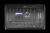
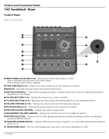
Control and Connection Panels T4S ToneMatch® Mixer Control Panel Figure 1. T4S Control Panel q w d e s r t a y f u o i q INPUT SIGNAL/CLIP LEDs (1-4) - Displays the input signal status in color: Green: Indicates the presence of an input signal Red: Indicates input source clipping w TRIM CONTROLS (1-4) - Adjusts the input sensitivity for the respective channel. e DISPLAY - Provides function menus and system information. r EDITING CONTROLS - These three rotary/push-button controls allow you to select or adjust items/values appearing on the display. t CH EDIT BUTTONS (1-4) - Selects the channel you want to modify. y FX MUTE BUTTONS (1-4) - Bypasses the Mod, Delay, and Reverb effects on the selected channel. u VOLUME CONTROLS (1-4) - Adjusts the volume level for the respective channel. i MUTE BUTTONS (1-4) - Silences the audio output for the respective channel. o MASTER VOLUME CONTROL - Adjusts the overall output level. a HEADPHONE VOLUME CONTROL - Adjusts the volume level of the headphone output. s ROTARY SELECTOR - Allows access to both global and channel-related parameters, which are adjusted using the editing controls. d PHANTOM POWER SWITCH - Applies +48V power to input channels 1-4. A red LED indicates that phantom power is on. f HEADPHONE JACK - For use with headphones only, with a minimum impedance of 24Ω. 6 - English
-
 1
1 -
 2
2 -
 3
3 -
 4
4 -
 5
5 -
 6
6 -
 7
7 -
 8
8 -
 9
9 -
 10
10 -
 11
11 -
 12
12 -
13
-
14
-
15
-
16
-
17
-
18
-
19
-
20
-
21
-
22
-
23
-
24
-
25
-
26
-
27
-
28
-
29
-
30
-
31
-
32
-
33
-
34
-
35
-
36
-
37
-
38
-
39
-
40
-
41
-
42
-
43
-
44
-
45
-
46
-
47
-
48
 |
 |
