Brother International HL 2060 Service Manual - Page 94
Cover Open
 |
UPC - 012502525325
View all Brother International HL 2060 manuals
Add to My Manuals
Save this manual to your list of manuals |
Page 94 highlights
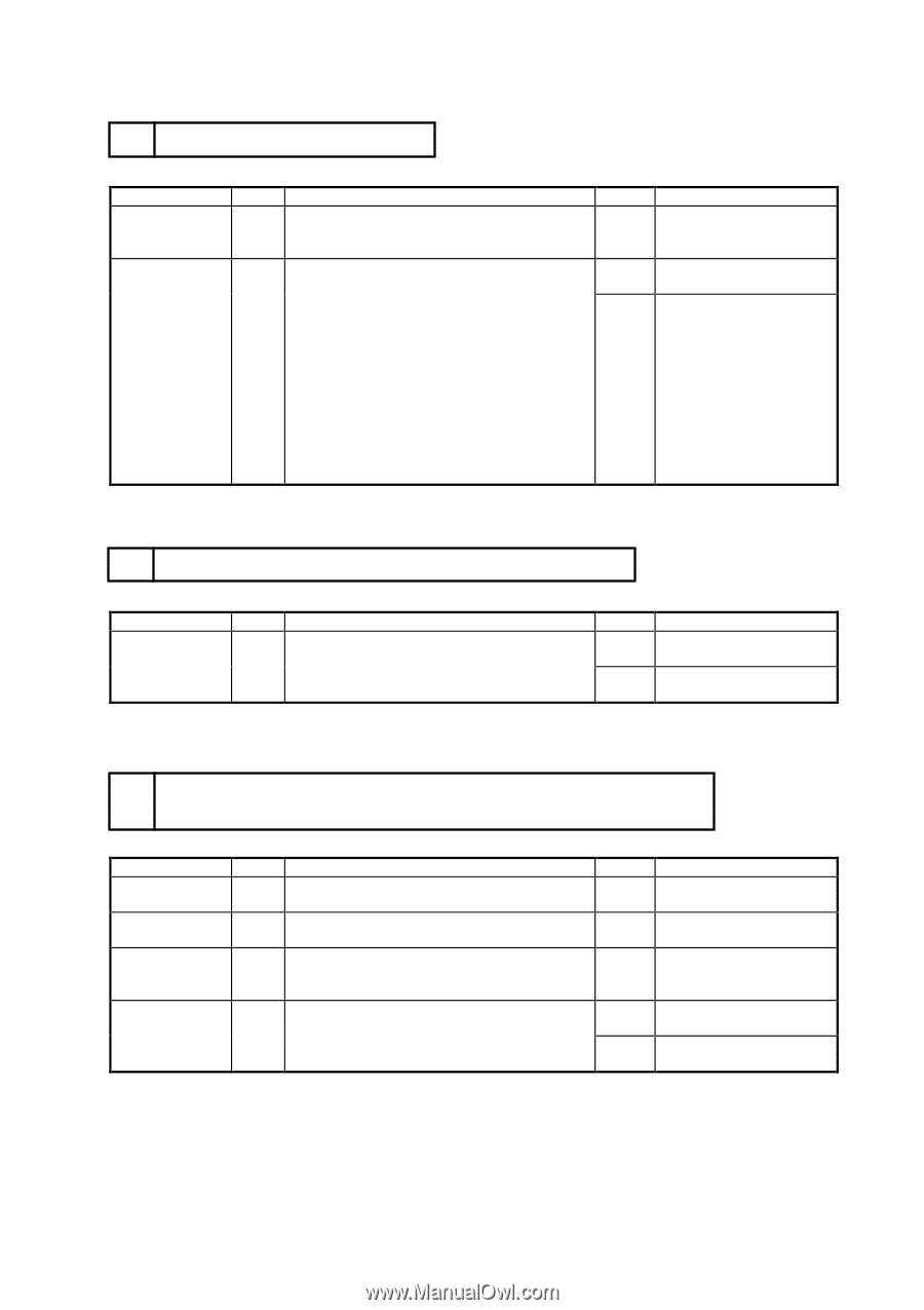
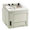
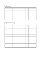
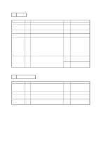
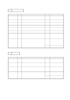
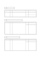
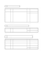
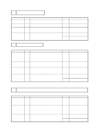
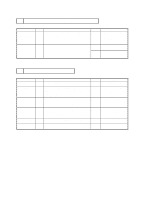
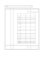
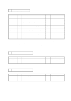
M-4 Malfunction of control panel switches Possible cause Mis-operation Switch Control panel PCB Switch flat cable Main PCB Step 1 2 Check Are the switches operated according to the operation manual? Result No When a switch is pressed, does the voltage of Yes the following signals change from 5V to 0V? No Signal Main PCB Panel PCB SW8(SEL) P1-7 − P1-7 SW7(MODE/EMULATION) P1-19 − P1-19 SW6(FONT/ECONOMY) P1-9 − P1-9 SW5(FORM FEED/FEEDER) P1-5 − P1-5 SW4(SET/COPY) P1-15 − P1-15 SW3(CONTINUE/SHIFT) P1-17 − P1-17 SW2(DOWN/RESET) P1-13 − P1-13 SW1(UP/TEST) P1-11 − P1-11 Remedy Operate the switches correctly following the operation manual. Replace the Main PCB assy. Replace the control panel unit or the switch flat cable. M-5 "12 COVER OPEN " is displayed even if the upper cover is closed Possible cause Upper cover Main PCB Step 1 Check Does the upper cover hook press the actuator of the interlock switch on the main PCB correctly when upper cover is closed? Result No Yes Remedy Replace the upper cover assy. Replace the main PCB assy. M-6 "CHECK XX TRAY" is displayed even if a paper-loaded cassette is mounted (or even if a paper is set on MP tray) XX is MP/T1/T2 Possible cause Mis-operation Actuator Paper empty sensor Feed flat cable Paper feed flat cable Main PCB Step Check 1 Is the paper feed mode set correctly? 2 Does the actuator for the paper empty sensor operate smoothly? 3 Does the voltage of P5-3 (or P5-14) in the Paper feeder PCB connector rise from 0V to 5V when the paper empty sensor is covered? 4 Does the voltage of P3-3 (or P3-14) in the main PCB connector rise from 0V to 5V when the paper empty sensor is covered? Result No No No No Yes Remedy Set paper feed mode correctly. Reassemble or replace the actuator. Replace the paper feed/size-sw PCB assy or feed flat cable. Replace the feed flat cable. Replace the main PCB assy. VI-12
-
 1
1 -
2
-
3
-
4
-
5
-
6
-
7
-
8
-
9
-
10
-
11
-
12
-
13
-
14
-
15
-
16
-
17
-
18
-
19
-
20
-
21
-
22
-
23
-
24
-
25
-
26
-
27
-
28
-
29
-
30
-
31
-
32
-
33
-
34
-
35
-
36
-
37
-
38
-
39
-
40
-
41
-
42
-
43
-
44
-
45
-
46
-
47
-
48
-
49
-
50
-
51
-
52
-
53
-
54
-
55
-
56
-
57
-
58
-
59
-
60
-
61
-
62
-
63
-
64
-
65
-
66
-
67
-
68
-
69
-
70
-
71
-
72
-
73
-
74
-
75
-
76
-
77
-
78
-
79
-
80
-
81
-
82
-
83
-
84
-
85
-
86
-
87
-
88
-
 89
89 -
 90
90 -
 91
91 -
 92
92 -
 93
93 -
 94
94 -
 95
95 -
 96
96 -
 97
97 -
 98
98 -
 99
99 -
100
-
101
-
102
-
103
-
104
-
105
-
106
-
107
-
108
-
109
-
110
-
111
-
112
-
113
-
114
-
115
-
116
-
117
-
118
-
119
-
120
-
121
-
122
-
123
-
124
-
125
-
126
-
127
-
128
-
129
-
130
-
131
-
132
-
133
-
134
-
135
-
136
-
137
-
138
-
139
-
140
-
141
-
142
-
143
-
144
-
145
-
146
-
147
-
148
-
149
-
150
-
151
-
152
-
153
-
154
-
155
-
156
-
157
-
158
-
159
-
160
-
161
-
162
-
163
-
164
-
165
-
166
-
167
-
168
-
169
-
170
-
171
 |
 |