Brother International HL 2060 Service Manual - Page 98
About 55 HIGH VOL MALF
 |
UPC - 012502525325
View all Brother International HL 2060 manuals
Add to My Manuals
Save this manual to your list of manuals |
Page 98 highlights
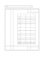
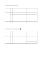
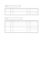
About 55 HIGH VOL MALF PR99033 HV MALF occurs under the following conditions. a. When the resistance of the transfer roller is too low. b. When the Developing AC bias is not applied. The reason for low resistance of the Transfer roller is the following cases. - Paper dust or toner adhered to the roller. - High humidity circumstance Low resistance induces poor quality printing, therefore the machine checks it before every print job. < How to check the resistance > The resistance can be checked with a hidden function "TRBIAS V0 TEST". (Refer to page VII-4) - Measurement point No.9 pin (HVT4) of the P6 connector on the MAIN PCB (not constant output) - HVT4 signal Machine status HVT4 (V) Ready: 0 Main motor ON -- Pre-setting 0 -- paper comes to transfer roller: X While transferring: Y Between a paper and next paperX Treatment -- Main motor OFF: 0 - X, Y voltage While pre-setting, the HVPS flow the constant-current 2µA to the Transfer roller and the Engine CPU monitor the transfer voltage. The Engine CPU fix the voltage X and Y based on the transfer voltage. It means that the voltage X and Y may vary based on the resistance of the Transfer roller. Normally, the voltage X is in the range 1 - 4 V. - When HV MALF occurs ? When the voltage X is below 0.27 V, the Engine CPU recognise the resistance of the Transfer roller is too low and warn the user with displaying "55 HIGH VOL MALF". If the voltage X is known, the resistance of the Transfer roller can roughly be guessed. Approx. 1.0 V = 600 Mohm (Bottom limit) Approx. 3.5 V = 6000 Mohm (Upper limit) On the part specification, the resistance of the Transfer roller is stated as below. ( For the measurement, the special jig and the equipment are necessary.) 600 Mohm - 6000 Mohm (Flow current measured while 2 kV applied.) VI-15-1
-
 1
1 -
2
-
3
-
4
-
5
-
6
-
7
-
8
-
9
-
10
-
11
-
12
-
13
-
14
-
15
-
16
-
17
-
18
-
19
-
20
-
21
-
22
-
23
-
24
-
25
-
26
-
27
-
28
-
29
-
30
-
31
-
32
-
33
-
34
-
35
-
36
-
37
-
38
-
39
-
40
-
41
-
42
-
43
-
44
-
45
-
46
-
47
-
48
-
49
-
50
-
51
-
52
-
53
-
54
-
55
-
56
-
57
-
58
-
59
-
60
-
61
-
62
-
63
-
64
-
65
-
66
-
67
-
68
-
69
-
70
-
71
-
72
-
73
-
74
-
75
-
76
-
77
-
78
-
79
-
80
-
81
-
82
-
83
-
84
-
85
-
86
-
87
-
88
-
89
-
90
-
91
-
92
-
 93
93 -
 94
94 -
 95
95 -
 96
96 -
 97
97 -
 98
98 -
 99
99 -
 100
100 -
 101
101 -
 102
102 -
 103
103 -
104
-
105
-
106
-
107
-
108
-
109
-
110
-
111
-
112
-
113
-
114
-
115
-
116
-
117
-
118
-
119
-
120
-
121
-
122
-
123
-
124
-
125
-
126
-
127
-
128
-
129
-
130
-
131
-
132
-
133
-
134
-
135
-
136
-
137
-
138
-
139
-
140
-
141
-
142
-
143
-
144
-
145
-
146
-
147
-
148
-
149
-
150
-
151
-
152
-
153
-
154
-
155
-
156
-
157
-
158
-
159
-
160
-
161
-
162
-
163
-
164
-
165
-
166
-
167
-
168
-
169
-
170
-
171
 |
 |
