Canon BJC-2000 Series Service Manual - Page 70
Part 4: Technical Reference, 2 Print Signal Flow
 |
View all Canon BJC-2000 Series manuals
Add to My Manuals
Save this manual to your list of manuals |
Page 70 highlights
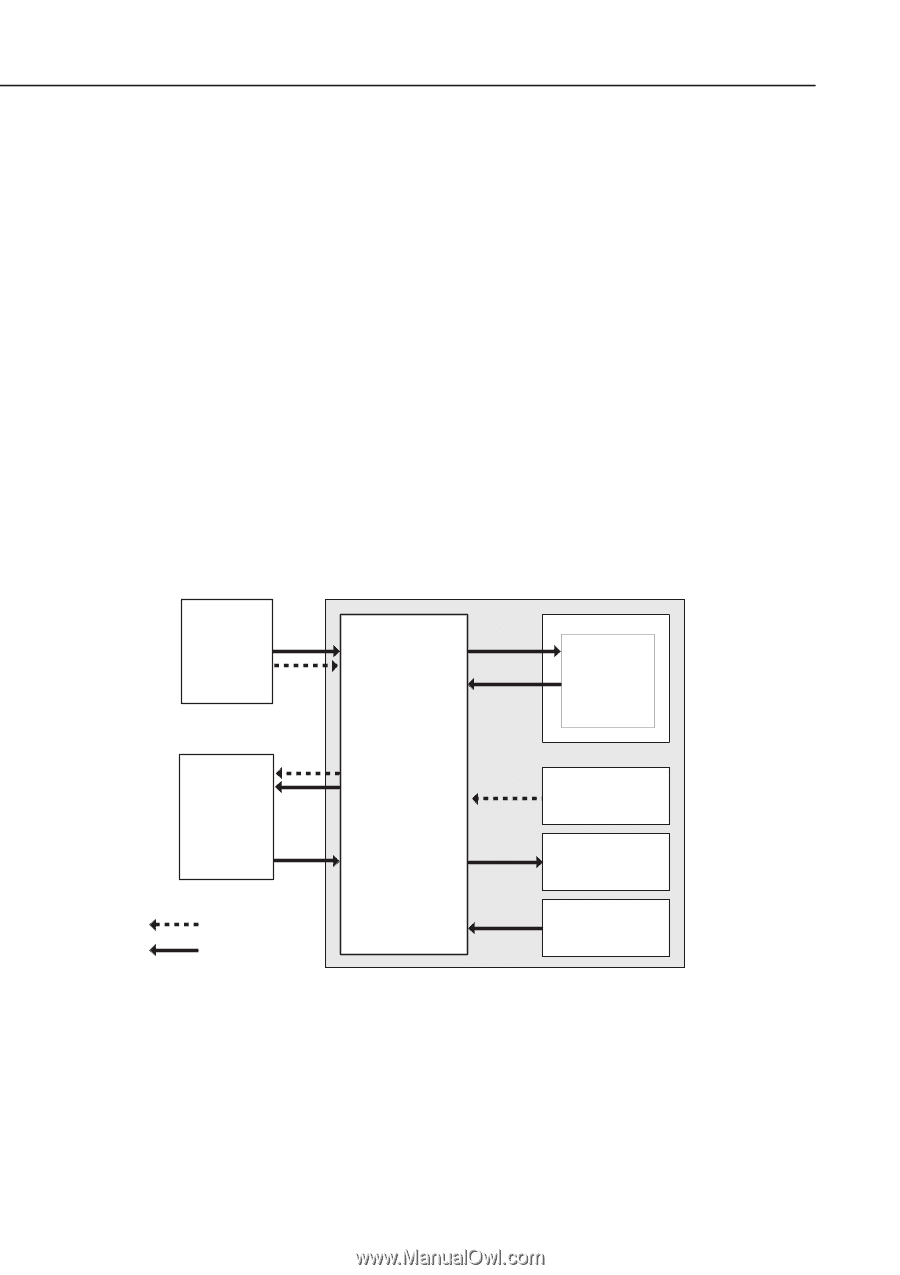
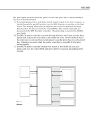
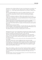
Part 4: Technical Reference BJC-2000 1.2 Print Signal Flow The print signal flow from when the printer receives the print data to when printing is executed is described below. a) The printing information, including control signals output by the host computer, is loaded through the parallel interface into the MPU & printer controller on the logic board. The printing information is separated into control commands and print data based on the data stored in the control ROM. The control commands are processed in the MPU & printer controller. The print data is stored in the DRAM print buffer. b) The MPU & printer controller converts the print data into serial data as print drive signals and outputs the serial data to the bubble jet head. In the bubble jet head, the print data is converted from serial signals to parallel print data for each printed line. Printing is executed while the printer controller is controlled by the print control signals. c) The MPU & printer controller monitors the status of the bubble jet head and printer and uses the control ROM and motor drivers to manage all printing driver controls. Host a Computer DRAM a b Print Buffer BJ Head b MPU & Printer Controller a c c Logic Board Control ROM Motor Drivers : Print signal : Control signal c Sensors Figure 4-2 Printing Signal Flow 4-2
-
 1
1 -
2
-
3
-
4
-
5
-
6
-
7
-
8
-
9
-
10
-
11
-
12
-
13
-
14
-
15
-
16
-
17
-
18
-
19
-
20
-
21
-
22
-
23
-
24
-
25
-
26
-
27
-
28
-
29
-
30
-
31
-
32
-
33
-
34
-
35
-
36
-
37
-
38
-
39
-
40
-
41
-
42
-
43
-
44
-
45
-
46
-
47
-
48
-
49
-
50
-
51
-
52
-
53
-
54
-
55
-
56
-
57
-
58
-
59
-
60
-
61
-
62
-
63
-
64
-
 65
65 -
 66
66 -
 67
67 -
 68
68 -
 69
69 -
 70
70 -
 71
71 -
 72
72 -
 73
73 -
 74
74 -
 75
75 -
76
-
77
-
78
-
79
-
80
-
81
-
82
-
83
-
84
-
85
-
86
-
87
-
88
-
89
-
90
-
91
-
92
-
93
-
94
-
95
-
96
-
97
-
98
-
99
-
100
-
101
-
102
-
103
-
104
-
105
-
106
-
107
-
108
-
109
-
110
-
111
-
112
-
113
-
114
-
115
-
116
-
117
-
118
-
119
-
120
-
121
-
122
-
123
-
124
-
125
-
126
-
127
-
128
-
129
-
130
-
131
-
132
-
133
-
134
-
135
-
136
 |
 |