Canon FAXPHONE B170 Parts Catalog - Page 122
Guide, Replacement
 |
View all Canon FAXPHONE B170 manuals
Add to My Manuals
Save this manual to your list of manuals |
Page 122 highlights
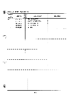
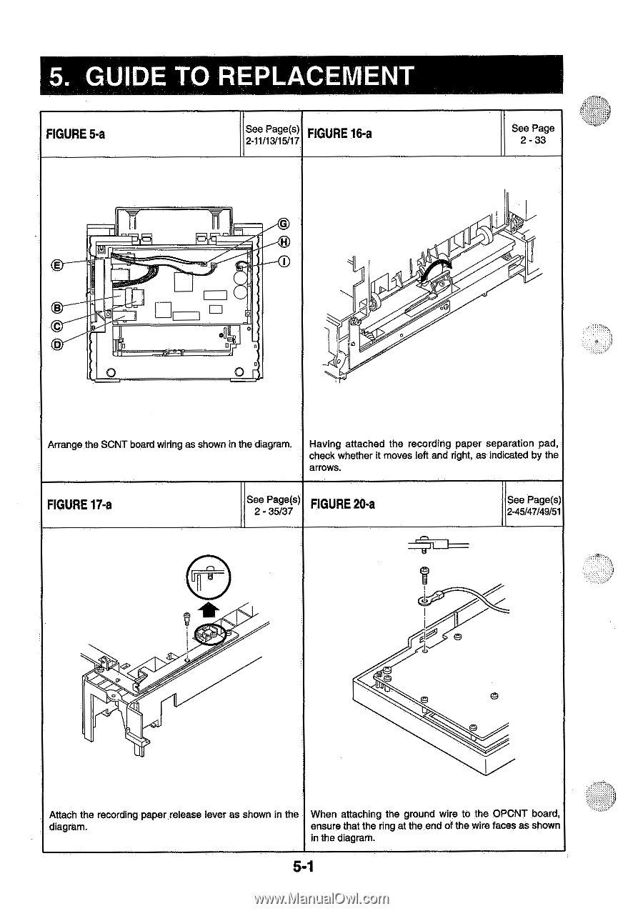
5. GUIDE TO REPLACEMENT FIGURE 5-a See Page(s) 2-11/13/15/17 FIGURE 16-a See Page 2 - 33 G E B C I D 0 O = O . O 0 OO 0 Arrange the SCNT board wiring as shown in the diagram. Having attached the recording paper separation pad, check whether it moves left and right, as indicated by the arrows. FIGURE 17-a See Page(s) 2 - 35/37 FIGURE 20-a See Page(s) 2-45/47/49/51 ii Y I 0. . lu ti gib 0 Attach the recording paper release lever as shown in the When attaching the ground wire to the OPCNT board, diagram. ensure that the ring at the end of the wire faces as shown in the diagram. 5-1
-
 1
1 -
2
-
3
-
4
-
5
-
6
-
7
-
8
-
9
-
10
-
11
-
12
-
13
-
14
-
15
-
16
-
17
-
18
-
19
-
20
-
21
-
22
-
23
-
24
-
25
-
26
-
27
-
28
-
29
-
30
-
31
-
32
-
33
-
34
-
35
-
36
-
37
-
38
-
39
-
40
-
41
-
42
-
43
-
44
-
45
-
46
-
47
-
48
-
49
-
50
-
51
-
52
-
53
-
54
-
55
-
56
-
57
-
58
-
59
-
60
-
61
-
62
-
63
-
64
-
65
-
66
-
67
-
68
-
69
-
70
-
71
-
72
-
73
-
74
-
75
-
76
-
77
-
78
-
79
-
80
-
81
-
82
-
83
-
84
-
85
-
86
-
87
-
88
-
89
-
90
-
91
-
92
-
93
-
94
-
95
-
96
-
97
-
98
-
99
-
100
-
101
-
102
-
103
-
104
-
105
-
106
-
107
-
108
-
109
-
110
-
111
-
112
-
113
-
114
-
115
-
116
-
 117
117 -
 118
118 -
 119
119 -
 120
120 -
 121
121 -
 122
122 -
 123
123 -
 124
124 -
 125
125 -
 126
126 -
 127
127 -
128
-
129
-
130
-
131
-
132
-
133
-
134
 |
 |
5.
GUIDE
TO
REPLACEMENT
FIGURE
5-a
See
Page(s)
2-11/13/15/17
FIGURE
16-a
See
Page
2
-
33
Having
check
arrows.
attached
whether
0
0
OO
the
recording
paper
separation
it
moves
left
and
right,
as
indicated
pad,
by
the
G
E
B
=
O
I
C
D
.
0
O
O
Arrange
the
SCNT
board
wiring
as
shown
in
the
diagram.
FIGURE
17-a
See
Page(s)
2
-
35/37
FIGURE
20-a
See
Page(s)
2-45/47/49/51
Attach
the
diagram.
0.
.
lu
recording
paper
ii
Y
I
release
lever
as
shown
in
the
When
attaching
ensure
that
in
the
diagram.
t
i
g
ib
0
the
ground
wire
to
the
OPCNT
board,
the
ring
at
the
end
of
the
wire
faces
as
shown
5-1