Canon FAXPHONE B170 Parts Catalog - Page 124
correctly
 |
View all Canon FAXPHONE B170 manuals
Add to My Manuals
Save this manual to your list of manuals |
Page 124 highlights
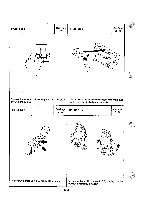
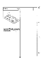
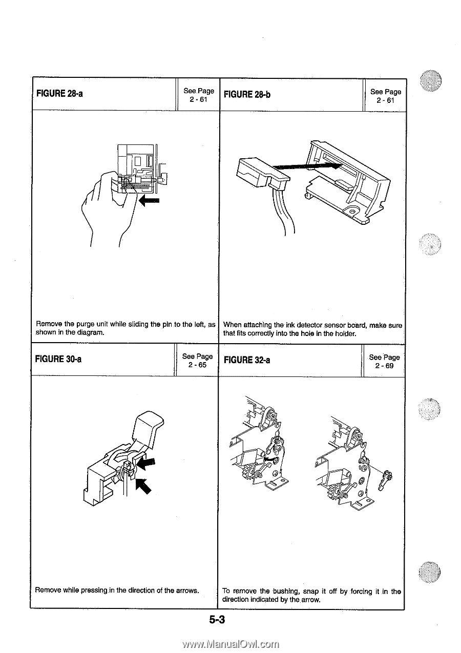
FIGURE 28-a See Page 2-61 FIGURE 28-b See Page 2-61 Remove the purge unit while sliding the pin to the left, as When attaching the ink detector sensor board, make sure shown in the diagram. that fits correctly into the hole in the holder. FIGURE 30-a See Page 2-65 FIGURE 32-a See Page 2-69 0 Remove while pressing in the direction of the arrows. To remove the bushing, snap it off by forcing it in the direction indicated by the arrow. 5-3
-
 1
1 -
2
-
3
-
4
-
5
-
6
-
7
-
8
-
9
-
10
-
11
-
12
-
13
-
14
-
15
-
16
-
17
-
18
-
19
-
20
-
21
-
22
-
23
-
24
-
25
-
26
-
27
-
28
-
29
-
30
-
31
-
32
-
33
-
34
-
35
-
36
-
37
-
38
-
39
-
40
-
41
-
42
-
43
-
44
-
45
-
46
-
47
-
48
-
49
-
50
-
51
-
52
-
53
-
54
-
55
-
56
-
57
-
58
-
59
-
60
-
61
-
62
-
63
-
64
-
65
-
66
-
67
-
68
-
69
-
70
-
71
-
72
-
73
-
74
-
75
-
76
-
77
-
78
-
79
-
80
-
81
-
82
-
83
-
84
-
85
-
86
-
87
-
88
-
89
-
90
-
91
-
92
-
93
-
94
-
95
-
96
-
97
-
98
-
99
-
100
-
101
-
102
-
103
-
104
-
105
-
106
-
107
-
108
-
109
-
110
-
111
-
112
-
113
-
114
-
115
-
116
-
117
-
118
-
 119
119 -
 120
120 -
 121
121 -
 122
122 -
 123
123 -
 124
124 -
 125
125 -
 126
126 -
 127
127 -
 128
128 -
 129
129 -
130
-
131
-
132
-
133
-
134
 |
 |
FIGURE
28-a
See
Page
2-61
FIGURE
28-b
See
Page
2-61
Remove
the
purge
unit
while
sliding
the
pin
to
the
left,
as
shown
in
the
diagram.
When
attaching
the
ink
detector
sensor
board,
make
sure
that
fits
correctly
into
the
hole
in
the
holder.
FIGURE
30-a
See
Page
2-65
FIGURE
32-a
See
Page
2-69
Remove
while
pressing
in
the
direction
of
the
arrows.
0
To
remove
the
bushing,
snap
it
off
by
forcing
it
in
the
direction
indicated
by
the
arrow.
5-3