Canon FAXPHONE B170 Parts Catalog - Page 6
About, Manual
 |
View all Canon FAXPHONE B170 manuals
Add to My Manuals
Save this manual to your list of manuals |
Page 6 highlights
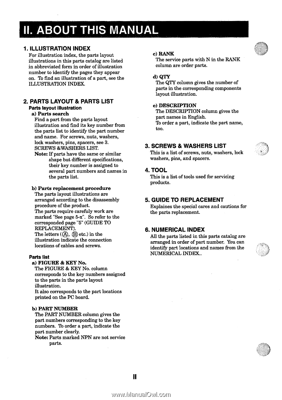
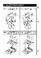
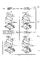
II. ABOUT THIS MANUAL 1. ILLUSTRATION INDEX For illustration index, the parts layout illustrations in this parts catalog are listed in abbreviated form in order of illustration number to identify the pages they appear on. To find an illustration of a part, see the ILLUSTRATION INDEX. 2. PARTS LAYOUT & PARTS LIST Parts layout illustration a) Parts search Find a part from the parts layout illustration and find its key number from the parts list to identify the part number and name. For screws, nuts, washers, lock washers, pins, spacers, see 3. SCREWS &WASHERS LIST. Note: If parts have the same or similar shape but different specifications, their key number is assigned to several part numbers and names in the parts list. b) Parts replacement procedure The parts layout illustrations are arranged according to the disassembly procedure of the product. The parts require carefuly work are marked "See page 5-f. So refer to the corresponded page "5" (GUIDE TO REPLACEMENT). The letters (C), etc.) in the illustration indicate the connection locations of cables and screws. Parts list a) FIGURE & KEY No. The FIGURE & KEY No. column corresponds to the key numbers assigned to the parts in the parts layout illustration. It also corresponds to the part locations printed on the PC board. b) PART NUMBER The PART NUMBER column gives the part numbers corresponding to the key numbers. To order a part, indicate the part number clearly. Note: Parts marked NPN are not service parts. c) RANK The service parts with N in the RANK column are order parts. d) QTY The QTY column gives the number of parts in the corresponding components layout illustration. e) DESCRIPTION The DESCRIPTION column gives the part names in English. To order a part, indicate the part name, too. 3. SCREWS & WASHERS LIST This is a list of screws, nuts, washers, lock washers, pins, and spacers. 4. TOOL This is a list of tools used for servicing products. 5. GUIDE TO REPLACEMENT Explaines the special cares and cautions for the parts replacement. 6. NUMERICAL INDEX All the parts listed in this parts catalog are arranged in order of part number. You can identify part locations and names from the NUMERICAL INDEX.. II
-
 1
1 -
 2
2 -
 3
3 -
 4
4 -
 5
5 -
 6
6 -
 7
7 -
 8
8 -
 9
9 -
 10
10 -
 11
11 -
 12
12 -
13
-
14
-
15
-
16
-
17
-
18
-
19
-
20
-
21
-
22
-
23
-
24
-
25
-
26
-
27
-
28
-
29
-
30
-
31
-
32
-
33
-
34
-
35
-
36
-
37
-
38
-
39
-
40
-
41
-
42
-
43
-
44
-
45
-
46
-
47
-
48
-
49
-
50
-
51
-
52
-
53
-
54
-
55
-
56
-
57
-
58
-
59
-
60
-
61
-
62
-
63
-
64
-
65
-
66
-
67
-
68
-
69
-
70
-
71
-
72
-
73
-
74
-
75
-
76
-
77
-
78
-
79
-
80
-
81
-
82
-
83
-
84
-
85
-
86
-
87
-
88
-
89
-
90
-
91
-
92
-
93
-
94
-
95
-
96
-
97
-
98
-
99
-
100
-
101
-
102
-
103
-
104
-
105
-
106
-
107
-
108
-
109
-
110
-
111
-
112
-
113
-
114
-
115
-
116
-
117
-
118
-
119
-
120
-
121
-
122
-
123
-
124
-
125
-
126
-
127
-
128
-
129
-
130
-
131
-
132
-
133
-
134
 |
 |