Casio IT-3000 User Guide - Page 26
Printer Terminal or with the Bridge Satellite Cradle. - paper roll
 |
UPC - 079767602345
View all Casio IT-3000 manuals
Add to My Manuals
Save this manual to your list of manuals |
Page 26 highlights
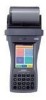
General Guide 1 SD Memory Card Slot Slot for inserting SD memory card. 2 Program Key (L) This key can be assigned any function available. IT-3000M55E/IT-3000M55U/IT-3000M56E/IT-3000M56U The default settings are as follows. This key is used to read bar codes and 2D code. 3 Roll Paper Holder Roll paper is placed in this holder. Use the optional Paper Holder when using a formed sheet paper. 4 Splash Protect Cover and Paper Cutter Printed roll paper is torn off here. The paper cutter is provided with a splash protect cover. Open the cover when printing. The paper cutter is revealed when the cover is opened. 5 Power Key Press this key to turn the power on or off. 6 Indicator 1 (Left Side) This indicator is green when charging the battery pack is completed and red during charging. Indicator 2 (Right Side) This indicator flashes or lights according to the settings of the application software. 7 Speaker Generates audio and buzzer tones. 8 Brightness Sensor This sensor detects the brightness of the surroundings. The display backlight and key backlight can be controlled automatically according to programmed settings. Be careful not to inadvertently block this sensor. 9 LCD Panel/Touch Screen Displays text, operations, indicators and so forth. In addition, operations can be performed and data can be input using the stylus provided. 10 Stroke Keys There are a total of 19 keys including function keys and numeric keys. Refer to "Key Functions" on page 26 for further details. Each numeral and symbol on the key buttons in the table above is backlit. 11 RS-232C Interface Connector (IT-3000M53E/ M54E2) For connection of a bar code reader and so forth. Connect by opening the connector cover. 12 Program Key (R) This key can be assigned any function available. IT-3000M55E/IT-3000M55U/IT-3000M56E/IT-3000M56U The default settings are as follows. This key is used to read bar codes and 2D codes. 13 Power Jack The AC adaptor is connected to this jack when charging the lithium ion battery pack. Open the jack cover to connect the AC adaptor. 14 IR Port This is used for IR data communication with another Handheld Printer Terminal or with the Bridge Satellite Cradle. E-24
-
 1
1 -
2
-
3
-
4
-
5
-
6
-
7
-
8
-
9
-
10
-
11
-
12
-
13
-
14
-
15
-
16
-
17
-
18
-
19
-
20
-
 21
21 -
 22
22 -
 23
23 -
 24
24 -
 25
25 -
 26
26 -
 27
27 -
 28
28 -
 29
29 -
 30
30 -
 31
31 -
32
-
33
-
34
-
35
-
36
-
37
-
38
-
39
-
40
-
41
-
42
-
43
-
44
-
45
-
46
-
47
-
48
-
49
-
50
-
51
-
52
-
53
-
54
-
55
-
56
-
57
-
58
-
59
-
60
-
61
-
62
-
63
-
64
-
65
-
66
-
67
-
68
-
69
-
70
-
71
-
72
-
73
-
74
-
75
-
76
-
77
-
78
-
79
 |
 |
