Celestron CGE Pro 1400 FASTAR Computerized Telescope CGE Pro Series Manual - Page 15
Adjusting the Mount
 |
View all Celestron CGE Pro 1400 FASTAR Computerized Telescope manuals
Add to My Manuals
Save this manual to your list of manuals |
Page 15 highlights
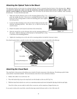
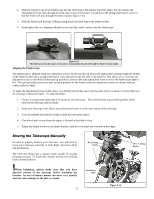
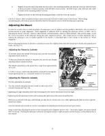
6. Slightly loosen the knobs that holds the telescope to the mounting platform and slide the telescope either forward or backward until it remains stationary when the DEC clutch is loose. Do NOT let go of the telescope tube while the knob on the mounting platform is loose. 7. Tighten the knobs on the telescope mounting platform to hold the telescope in place. Like R.A. balance, these are general balance instructions and will reduce undue stress on the mount. When taking astrophotographs, this balance process should be done for the specific area at which the telescope is pointing. Adjusting the Mount In order for a motor drive to track accurately, the telescope's axis of rotation must be parallel to the Earth's axis of rotation, a process known as polar alignment. Polar alignment is achieved NOT by moving the telescope in R.A. or DEC, but by adjusting the mount vertically, which is called altitude, and horizontally, which is called azimuth. This section simply covers the correct movement of the telescope during the polar alignment process. The actual process of polar alignment, that is making the telescope's axis of rotation parallel to the Earth's, is described later in this manual in the section on "Polar Alignment." Before adjusting the mount in altitude or azimuth you must first slightly loosen both the latitude pivot knobs and azimuth pivot knobs. See Fig 2-16. Adjusting the Mount in Latitude Latitude Pivot knobs • To increase (raise) the latitude of the polar axis, turn the rear latitude adjustment knob clockwise. • To decrease (lower) the latitude of the polar axis, turn the rear latitude adjustment knob counterclockwise. The latitude adjustment on the mount has a range from approximately 10° to 65°. Latitude Adjustment Knob Attachment Knobs It is best to always make final adjustments in latitude by moving the mount against gravity (i.e. raising the latitude of the mount). Adjusting the Mount in Azimuth Azimuth Pivot Knobs For fine adjustments in azimuth: 1. Turn the azimuth adjustment knobs located on either side of the azimuth housing (see Fig 2-16). Figure 2-16 • Tightening the right adjustment knob (and loosening the left) moves the mount toward the right. Azimuth Adjustment Knob • Tightening the left adjustment knob (and loosening the right) moves the mount toward the left. Both screws push off of the peg, which means you may have to loosen one screw while tightening the other in order to get the desired movement. Once the latitude and azimuth are correct, hand tighten the latitude pivot knobs and azimuth pivot knobs. Keep in mind that adjusting the mount is done during the polar alignment process only. Once polar aligned, the mount should NOT be moved. Pointing the telescope is done by moving the mount in right ascension and declination, as described earlier in this manual. 15
-
 1
1 -
2
-
3
-
4
-
5
-
6
-
7
-
8
-
9
-
 10
10 -
 11
11 -
 12
12 -
 13
13 -
 14
14 -
 15
15 -
 16
16 -
 17
17 -
 18
18 -
 19
19 -
 20
20 -
21
-
22
-
23
-
24
-
25
-
26
-
27
-
28
-
29
-
30
-
31
-
32
-
33
-
34
-
35
-
36
-
37
-
38
-
39
-
40
-
41
-
42
-
43
-
44
-
45
-
46
-
47
-
48
-
49
-
50
-
51
-
52
-
53
-
54
-
55
-
56
-
57
-
58
-
59
-
60
-
61
-
62
-
63
-
64
-
65
-
66
-
67
-
68
-
69
-
70
-
71
-
72
 |
 |
