Cisco 2501 Getting Started Guide - Page 16
situation to people and damage to the system.
 |
View all Cisco 2501 manuals
Add to My Manuals
Save this manual to your list of manuals |
Page 16 highlights
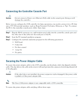
Warning Read the wall-mounting carefully before beginning installation. Failure to use the correct hardware or to follow the correct procedures could result in a hazardous situation to people and damage to the system. Statement 378 To mount the controller on a wall using mounting screws, follow these steps: Step 1 Mark the location of the mounting screws on the wall. Use the mount hole locations on the back of the controller for placement of the mounting screws (Figure 7). (The mount holes are shown in Figure 7 with a cross-hatch mark.) Figure 7 Mounting Screw Holes on the Back of the Controller 5.5 3.9 282087 FRONT PANEL Step 2 Step 3 Use a 0.107-inch (2.7mm) or #32 drill bit to drill a 3/4 inch (19mm) hole for the two mounting screws. Insert two screws into the screw holes and tighten until the top of the screws are 1/8 inch from the wall (leaving enough room for the back panel to slide onto the screws firmly). 16
-
 1
1 -
2
-
3
-
4
-
5
-
6
-
7
-
8
-
9
-
10
-
 11
11 -
 12
12 -
 13
13 -
 14
14 -
 15
15 -
 16
16 -
 17
17 -
 18
18 -
 19
19 -
 20
20 -
 21
21 -
22
-
23
-
24
-
25
-
26
-
27
-
28
-
29
-
30
-
31
-
32
-
33
-
34
-
35
-
36
-
37
-
38
-
39
-
40
-
41
-
42
-
43
-
44
-
45
-
46
-
47
-
48
-
49
-
50
-
51
-
52
-
53
-
54
-
55
-
56
 |
 |
