Cisco 2501 Getting Started Guide - Page 17
Step 4, Place the Controller on the Mounting Screws
 |
View all Cisco 2501 manuals
Add to My Manuals
Save this manual to your list of manuals |
Page 17 highlights
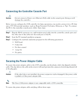
Step 4 Place the controller onto the mounting screws and slide it down until it lock into place, as shown in Figure 8. Note The front panel of the controller should be facing down. Figure 8 Place the Controller on the Mounting Screws 282085 2 1 2 1 Front panel (facing down) 2 Mounting screws Step 5 After the controller is mounted ion the wall, perform the following tasks to complete the installation: • Connecting the Controller Console Port • Securing the Power Adapter Cable • Connecting to the Network 17
-
 1
1 -
2
-
3
-
4
-
5
-
6
-
7
-
8
-
9
-
10
-
11
-
 12
12 -
 13
13 -
 14
14 -
 15
15 -
 16
16 -
 17
17 -
 18
18 -
 19
19 -
 20
20 -
 21
21 -
 22
22 -
23
-
24
-
25
-
26
-
27
-
28
-
29
-
30
-
31
-
32
-
33
-
34
-
35
-
36
-
37
-
38
-
39
-
40
-
41
-
42
-
43
-
44
-
45
-
46
-
47
-
48
-
49
-
50
-
51
-
52
-
53
-
54
-
55
-
56
 |
 |

17
Step 4
Place the controller onto the mounting screws and slide it down until it lock into place, as
shown in
Figure 8
.
Note
The front panel of the controller should be facing down.
Figure 8
Place the Controller on the Mounting Screws
Step 5
After the controller is mounted ion the wall, perform the following tasks to complete the
installation:
•
Connecting the Controller Console Port
•
Securing the Power Adapter Cable
•
Connecting to the Network
1
Front panel (facing down)
2
Mounting screws
282085
2
1
2