Cisco 2924M Hardware Installation Guide - Page 83
RJ-21 connectors, CAB-5-M120M120-5= Category 5 cable with 90-degree, male-to-male
 |
UPC - 746320186047
View all Cisco 2924M manuals
Add to My Manuals
Save this manual to your list of manuals |
Page 83 highlights
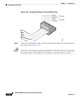
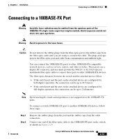
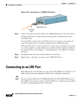
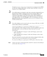
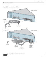
Chapter 2 Installation Connecting to an LRE Port If telephone services, such as voice or integrated services digital network (ISDN), use the same cabling as LRE traffic, you must connect the LRE to a plain old telephone service (POTS) splitter. Note Cisco LRE products are designed to share lines with analog, Integrated Services Digital Network (ISDN), and digital private branch exchange (PBX) switch telephones that use the 0 to 700 kHz frequency range. Digital telephones connected to digital PBX switches that use frequencies above 700 kHz do not work when sharing a line with LRE signals. Due to the proprietary nature of digital PBX switches, some digital PBX switch services use frequencies above 700 kHz. [CSCdu73260] Note If no other telephone services travel on the same wiring as LRE traffic, the LRE switch connects directly to a patch panel. Connecting the LRE port to a patch panel or POTS splitter requires a male-to-male RJ-21 cable, Category 3 or above. You can order RJ-21 cables from your cable vendor, or you can order these cables from your Cisco sales representative: • CAB-5-M120M120-5= (Category 5 cable with 90-degree, male-to-male RJ-21 connectors) • CAB-5-M180M120-5= (Category 5 cable with 120-degree, male-to-male RJ-21 connectors) The screws you need to secure the cable to the switch are shipped with the cable. Contact your Cisco sales representative for more information. To connect the LRE port to a patch panel or POTS splitter, follow these steps: Step 1 Connect one end of a wiring trunk cable to the RJ-21 connector of the LRE port on the switch. (See Figure 2-30.) 78-6461-04 Catalyst 2900 Series XL Hardware Installation Guide 2-39
-
 1
1 -
2
-
3
-
4
-
5
-
6
-
7
-
8
-
9
-
10
-
11
-
12
-
13
-
14
-
15
-
16
-
17
-
18
-
19
-
20
-
21
-
22
-
23
-
24
-
25
-
26
-
27
-
28
-
29
-
30
-
31
-
32
-
33
-
34
-
35
-
36
-
37
-
38
-
39
-
40
-
41
-
42
-
43
-
44
-
45
-
46
-
47
-
48
-
49
-
50
-
51
-
52
-
53
-
54
-
55
-
56
-
57
-
58
-
59
-
60
-
61
-
62
-
63
-
64
-
65
-
66
-
67
-
68
-
69
-
70
-
71
-
72
-
73
-
74
-
75
-
76
-
77
-
 78
78 -
 79
79 -
 80
80 -
 81
81 -
 82
82 -
 83
83 -
 84
84 -
 85
85 -
 86
86 -
 87
87 -
 88
88 -
89
-
90
-
91
-
92
-
93
-
94
-
95
-
96
-
97
-
98
-
99
-
100
-
101
-
102
-
103
-
104
-
105
-
106
-
107
-
108
-
109
-
110
-
111
-
112
-
113
-
114
-
115
-
116
-
117
-
118
-
119
-
120
-
121
-
122
-
123
-
124
-
125
-
126
-
127
-
128
-
129
-
130
-
131
-
132
-
133
-
134
-
135
-
136
-
137
-
138
-
139
-
140
-
141
-
142
-
143
-
144
-
145
-
146
-
147
-
148
-
149
-
150
-
151
-
152
-
153
-
154
-
155
-
156
-
157
-
158
-
159
-
160
-
161
-
162
 |
 |