Cisco 2924M Hardware Installation Guide - Page 86
Connecting to a Module Port, Connecting to the Console Port
 |
UPC - 746320186047
View all Cisco 2924M manuals
Add to My Manuals
Save this manual to your list of manuals |
Page 86 highlights
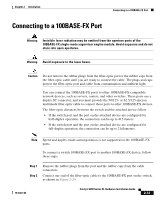
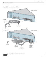
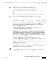
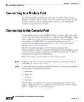
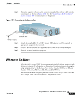
Connecting to a Module Port Chapter 2 Installation Connecting to a Module Port For information about installing and connecting to modules in the Catalyst 2924M XL and 2912MF XL module slots, refer to the Catalyst 2900 Series XL Modules Installation Guide and the Catalyst 2900 Series XL ATM Modules Installation and Configuration Guide. Connecting to the Console Port Use the supplied rollover cable and DB-9 adapter to connect a PC to the switch console port. You need to provide a RJ-45-to-DB-25 female DTE adapter if you want to connect the switch console port to a terminal. You can order a kit (part number ACS-DSBUASYN=) containing that adapter from Cisco. For console port and adapter pinout information, see the "Cable and Adapter Specifications" section on page B-4. The PC or terminal must support VT100 terminal emulation. The terminal-emulation software-frequently a PC application such as Hyperterminal or Procomm Plus-makes communication between the switch and your PC or terminal possible during the setup program. Follow these steps to connect the PC or terminal to the switch: Step 1 Step 2 Configure your PC- or terminal-emulation software to communicate with the switch through hardware flow control. Configure the baud rate and character format of the PC or terminal to match these switch console port default characteristics: • 9600 baud • 8 data bits • 1 stop bit • No parity After you have accessed the switch, you can change the port baud rate to its original setting. See the Catalyst 2900 Series XL and Catalyst 3500 Series XL Software Configuration Guide for instructions. 2-42 Catalyst 2900 Series XL Hardware Installation Guide 78-6461-04
-
 1
1 -
2
-
3
-
4
-
5
-
6
-
7
-
8
-
9
-
10
-
11
-
12
-
13
-
14
-
15
-
16
-
17
-
18
-
19
-
20
-
21
-
22
-
23
-
24
-
25
-
26
-
27
-
28
-
29
-
30
-
31
-
32
-
33
-
34
-
35
-
36
-
37
-
38
-
39
-
40
-
41
-
42
-
43
-
44
-
45
-
46
-
47
-
48
-
49
-
50
-
51
-
52
-
53
-
54
-
55
-
56
-
57
-
58
-
59
-
60
-
61
-
62
-
63
-
64
-
65
-
66
-
67
-
68
-
69
-
70
-
71
-
72
-
73
-
74
-
75
-
76
-
77
-
78
-
79
-
80
-
 81
81 -
 82
82 -
 83
83 -
 84
84 -
 85
85 -
 86
86 -
 87
87 -
 88
88 -
 89
89 -
 90
90 -
 91
91 -
92
-
93
-
94
-
95
-
96
-
97
-
98
-
99
-
100
-
101
-
102
-
103
-
104
-
105
-
106
-
107
-
108
-
109
-
110
-
111
-
112
-
113
-
114
-
115
-
116
-
117
-
118
-
119
-
120
-
121
-
122
-
123
-
124
-
125
-
126
-
127
-
128
-
129
-
130
-
131
-
132
-
133
-
134
-
135
-
136
-
137
-
138
-
139
-
140
-
141
-
142
-
143
-
144
-
145
-
146
-
147
-
148
-
149
-
150
-
151
-
152
-
153
-
154
-
155
-
156
-
157
-
158
-
159
-
160
-
161
-
162
 |
 |
