Cisco 2955T 12 Hardware Installation Guide - Page 100
/100/1000 Ports, Connecting to 10BASE-T and 100BASE-TX Devices, B-2, SFP Module Slots
 |
UPC - 746320783277
View all Cisco 2955T 12 manuals
Add to My Manuals
Save this manual to your list of manuals |
Page 100 highlights
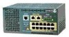
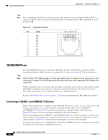
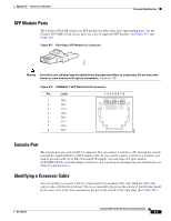
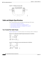
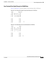
Connector Specifications Appendix B Connectors and Cables Note Use a straight-through cable to connect two ports only when one port is designated with an X. Use a crossover cable to connect two ports when both ports are designated with an X or when both ports do not have an X. Figure B-1 10/100 RJ-45 Pinouts Pin Label 1 RD+ 2 RD- 3 TD+ 4 NC 5 NC 6 TD- 7 NC 8 NC 12345678 H5318 10/100/1000 Ports The 10/100/1000 Ethernet ports on Catalyst 2950T-24, Catalyst 2950T-48-SI, and Catalyst 2950 Long-Reach Ethernet (LRE) switches use standard RJ-45 connectors. Figure B-2 shows the pinout. Note On the Catalyst 2950 LRE switches, the four input uplink ports are bundled as two logical ports, each consisting of a copper 10/100/1000 port and a fiber-optic small form-factor pluggable (SFP) module slot, respectively. Within each logical port, you can use only the copper or the fiber-optic port at one time. If the Catalyst 2950 LRE switch senses more than two connections for both logical ports, the switch chooses the fiber-optic connections over the copper connections in default operation. See the "SFP Module Slots" section on page 1-11 for more information on LRE uplink logical ports. Connecting to 10BASE-T and 100BASE-TX Devices When connecting the ports to 10BASE-T and 100BASE-TX devices, such as servers, workstations, and routers, you can use a two or four twisted-pair, straight-through cable wired for 10BASE-T and100BASE-TX. Figure B-10 shows the two twisted-pair, straight-through cable schematics. Figure B-12 shows the four twisted-pair, straight-through cable schematics. When connecting the ports to 10BASE-T- and 100BASE-TX devices, such as switches or repeaters, you can use a two or four twisted-pair, crossover cable. Figure B-11 shows the two twisted-pair, crossover cable schematics. Figure B-13 shows the four twisted-pair, crossover cable schematics. You can use Category 3, 4, or 5 cabling when connecting to 10BASE-T devices. You must use Category 5 cabling when connecting to 100BASE-TX devices. Catalyst 2950 Switch Hardware Installation Guide B-2 OL-6156-01
-
 1
1 -
2
-
3
-
4
-
5
-
6
-
7
-
8
-
9
-
10
-
11
-
12
-
13
-
14
-
15
-
16
-
17
-
18
-
19
-
20
-
21
-
22
-
23
-
24
-
25
-
26
-
27
-
28
-
29
-
30
-
31
-
32
-
33
-
34
-
35
-
36
-
37
-
38
-
39
-
40
-
41
-
42
-
43
-
44
-
45
-
46
-
47
-
48
-
49
-
50
-
51
-
52
-
53
-
54
-
55
-
56
-
57
-
58
-
59
-
60
-
61
-
62
-
63
-
64
-
65
-
66
-
67
-
68
-
69
-
70
-
71
-
72
-
73
-
74
-
75
-
76
-
77
-
78
-
79
-
80
-
81
-
82
-
83
-
84
-
85
-
86
-
87
-
88
-
89
-
90
-
91
-
92
-
93
-
94
-
 95
95 -
 96
96 -
 97
97 -
 98
98 -
 99
99 -
 100
100 -
 101
101 -
 102
102 -
 103
103 -
 104
104 -
 105
105 -
106
-
107
-
108
-
109
-
110
-
111
-
112
-
113
-
114
-
115
-
116
-
117
-
118
-
119
-
120
-
121
-
122
-
123
-
124
-
125
-
126
-
127
-
128
-
129
-
130
-
131
-
132
-
133
-
134
 |
 |
