Cisco 2955T 12 Hardware Installation Guide - Page 125
Step 8, If you enter
 |
UPC - 746320783277
View all Cisco 2955T 12 manuals
Add to My Manuals
Save this manual to your list of manuals |
Page 125 highlights
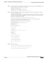
Appendix D Configuring the Switch with the CLI-Based Setup Program Entering the Initial Configuration Information Step 8 Configure the interface by entering the switch IP address and subnet mask and pressing Return. The IP address and subnet masks shown below are examples. Configuring interface vlan1: Configure IP on this interface? [yes]: yes IP address for this interface: 10.4.120.106 Subnet mask for this interface [255.0.0.0]: 255.0.0.0 Step 9 Enter Y to configure the switch as the cluster command switch. Enter N to configure it as a member switch or as a standalone switch. If you enter N, the switch appears as a candidate switch in the Network Assistant GUI. You can configure the switch as a command switch later through the CLI, the device manager, or the Network Assistant application. To configure it later, enter no. Would you like to enable as a cluster command switch? [yes/no]: no You have now completed the initial configuration of the switch, and the switch displays that configuration. This is an example of the output that appears: The following configuration command script was created: hostname host_name enable secret 5 $1$Max7$Qgr9eXBhtcBJw3KK7bc850 enable password my line vty 0 15 password my_password snmp-server community public ! no ip routing ! interface Vlan1 no shutdown ip address 172.20.139.145 255.255.255.224 ! interface Vlan2 shutdown no ip address ! interface FastEthernet0/1 ! interface FastEthernet0/2 ! ... !!! interface GigabitEthernet0/1 ! interface GigabitEthernet0/2 ! end Step 10 These choices appear: [0] Go to the IOS command prompt without saving this config. [1] Return back to the setup without saving this config. [2] Save this configuration to nvram and exit. OL-6156-01 Catalyst 2950 Switch Hardware Installation Guide D-7
-
 1
1 -
2
-
3
-
4
-
5
-
6
-
7
-
8
-
9
-
10
-
11
-
12
-
13
-
14
-
15
-
16
-
17
-
18
-
19
-
20
-
21
-
22
-
23
-
24
-
25
-
26
-
27
-
28
-
29
-
30
-
31
-
32
-
33
-
34
-
35
-
36
-
37
-
38
-
39
-
40
-
41
-
42
-
43
-
44
-
45
-
46
-
47
-
48
-
49
-
50
-
51
-
52
-
53
-
54
-
55
-
56
-
57
-
58
-
59
-
60
-
61
-
62
-
63
-
64
-
65
-
66
-
67
-
68
-
69
-
70
-
71
-
72
-
73
-
74
-
75
-
76
-
77
-
78
-
79
-
80
-
81
-
82
-
83
-
84
-
85
-
86
-
87
-
88
-
89
-
90
-
91
-
92
-
93
-
94
-
95
-
96
-
97
-
98
-
99
-
100
-
101
-
102
-
103
-
104
-
105
-
106
-
107
-
108
-
109
-
110
-
111
-
112
-
113
-
114
-
115
-
116
-
117
-
118
-
119
-
 120
120 -
 121
121 -
 122
122 -
 123
123 -
 124
124 -
 125
125 -
 126
126 -
 127
127 -
 128
128 -
 129
129 -
 130
130 -
131
-
132
-
133
-
134
 |
 |