Cisco AIR-BR1310G-E-K9 Hardware Installation Guide - Page 44
Cisco, IOS Software Configuration Guide for Access Points, Cisco Wireless LAN Controller
 |
View all Cisco AIR-BR1310G-E-K9 manuals
Add to My Manuals
Save this manual to your list of manuals |
Page 44 highlights
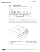
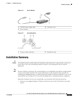
Installation Summary Chapter 2 Installation Overview • For outdoor installations, connect the dual-coax Ethernet cables between the power injector and the grounding block. For indoor installations, connect the dual-coax cables to the power injector. Tip You can connect the dual-coax cable connectors to either of the grounding block connectors or the power injector's dual-coax Ethernet ports. The access point/bridge senses the Ethernet signals and automatically switches internal circuitry to match the cable connections. Note You should securely tighten the cable connectors (15 to 20 inch-pounds) using a small wrench. • For outdoor installations, connect a ground wire to the grounding block. • Mount the access point/bridge to the mast, tower, or wall. For additional information, refer to the mounting instructions that shipped with your access point/bridge. Warning This equipment must be grounded. Never defeat the ground conductor or operate the equipment in the absence of a suitably installed ground conductor. Contact the appropriate electrical inspection authority or an electrician if you are uncertain that suitable grounding is available. Statement 1024 • Connect a ground wire to the access point/bridge (use the ground lug). • For outdoor installations, connect the dual-coax Ethernet cables to the grounding block and to the access point/bridge. For indoor installations, connect the dual-coax cables directly to the access point/bridge. Tip You can connect the dual-coax cable connectors to either of the grounding block connectors or the access point/bridge's dual-coax ports. The access point/bridge senses the Ethernet signals and automatically switches internal circuitry to match the cable connections. Note You should securely tighten the cable connectors (15 to 20 inch-pounds) using a small wrench. Warning This product relies on the building's installation for short-circuit (overcurrent) protection. Ensure that the protective device is rated not greater than: 20A Statement 1005 • For indoor installations, connect these items: - The AC power cord to the 48-VDC power module. - The power module power plug to the power injector and plug the AC cord into an AC power receptacle. • For outdoor installations, refer to the mounting instruction document that shipped with your access point/bridge. • Seal all external connectors with special weather sealing material. Configure security and other access point/bridge options. For additional information, refer to the Cisco IOS Software Configuration Guide for Access Points or the Cisco Wireless LAN Controller Configuration Guide. 2-10 Cisco Aironet 1300 Series Wireless Outdoor Access Point/Bridge Hardware Installation Guide OL-5048-06
-
 1
1 -
2
-
3
-
4
-
5
-
6
-
7
-
8
-
9
-
10
-
11
-
12
-
13
-
14
-
15
-
16
-
17
-
18
-
19
-
20
-
21
-
22
-
23
-
24
-
25
-
26
-
27
-
28
-
29
-
30
-
31
-
32
-
33
-
34
-
35
-
36
-
37
-
38
-
 39
39 -
 40
40 -
 41
41 -
 42
42 -
 43
43 -
 44
44 -
 45
45 -
 46
46 -
 47
47 -
 48
48 -
 49
49 -
50
-
51
-
52
-
53
-
54
-
55
-
56
-
57
-
58
-
59
-
60
-
61
-
62
-
63
-
64
-
65
-
66
-
67
-
68
-
69
-
70
-
71
-
72
-
73
-
74
-
75
-
76
-
77
-
78
-
79
-
80
-
81
-
82
-
83
-
84
-
85
-
86
-
87
-
88
-
89
-
90
-
91
-
92
-
93
-
94
-
95
-
96
-
97
-
98
-
99
-
100
-
101
-
102
-
103
-
104
-
105
-
106
-
107
-
108
-
109
-
110
-
111
-
112
-
113
-
114
-
115
-
116
-
117
-
118
 |
 |
