Cisco PIX 506E User Guide
Cisco PIX 506E - Security Appliance Manual
 |
UPC - 746320661315
View all Cisco PIX 506E manuals
Add to My Manuals
Save this manual to your list of manuals |
Cisco PIX 506E manual content summary:
- Cisco PIX 506E | User Guide - Page 1
section describes the PIX 506/506E front and rear panels and the panel LEDs. Figure 3-1 shows the front view of the PIX 506/506E. Figure 3-1 PIX 506/506E Front Panel 67945 POWER ACT NETWORK CISCO PIX 506E F I R E WA L L 78-15170-02 Cisco PIX Security Appliance Hardware Installation Guide 3-1 - Cisco PIX 506E | User Guide - Page 2
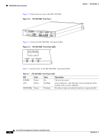
3-1 lists the states of the PIX 506/506E front panel LEDs. Table 3-1 PIX 506/506E Front Panel LEDs LED POWER ACT Color Green Green NETWORK Green State On Flashing Flashing Description The unit has power. Active indicator-On when the software image has been loaded on the security appliance. On - Cisco PIX 506E | User Guide - Page 3
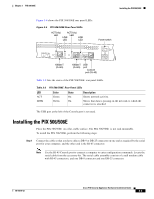
-45 Console port to connect a computer to enter configuration commands. Locate the serial cable from the accessory kit. The serial cable assembly consists of a null modem cable with RJ-45 connectors, and one DB-9 connector and one DB-25 connector. 78-15170-02 Cisco PIX Security Appliance Hardware - Cisco PIX 506E | User Guide - Page 4
document. The PIX 506/506E uses an external AC to DC power supply. Power is supplied to the PIX 506/506E by connecting the power supply to the back of the security appliance and connecting a separate AC power cord to the power supply. Cisco PIX Security Appliance Hardware Installation Guide 3-4 78 - Cisco PIX 506E | User Guide - Page 5
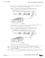
. Connect the power supply to the back of the PIX 506/506E. See Figure 3-6 for the PIX 506 and Figure 3-7 for the PIX 506E. When you are ready to start the PIX 506/506E, power on the unit from the switch at the rear of the unit. 78-15170-02 Cisco PIX Security Appliance Hardware Installation Guide - Cisco PIX 506E | User Guide - Page 6
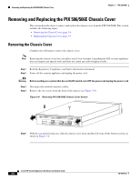
119681 ACT LINK ETHERNET 1 ACT LINK ETHERNET 0 USB CONSOLE DC POWER INPUT Step 5 With the rear panel facing you, slide the chassis cover back and then lift it up off the bottom section, as shown in Figure 3-8. Cisco PIX Security Appliance Hardware Installation Guide 3-6 78-15170-02 - Cisco PIX 506E | User Guide - Page 7
with the screws you set aside earlier. Reconnect the network interface cables. Place the PIX 506/506E on a flat, stable surface. The PIX 506/506E is not rack mountable. Reconnect the power cord and power on the security appliance. Replacing a Lithium Battery The PIX 506/506E has a lithium battery - Cisco PIX 506E | User Guide - Page 8
into the side and front panel slots on the chassis. Replace the chassis cover as described in the "Replacing the Chassis Cover" section on page 3-7. Cisco PIX Security Appliance Hardware Installation Guide 3-8 78-15170-02
-
 1
1 -
 2
2 -
 3
3 -
 4
4 -
 5
5 -
 6
6 -
 7
7 -
8
 |
 |
CH A P T E R
3-1
Cisco PIX Security Appliance Hardware Installation Guide
78-15170-02
3
PIX 506/506E
This chapter describes how to install a PIX 506/506E, and includes the following sections:
•
PIX 506/506E Product Overview, page 3-1
•
Installing the PIX 506/506E, page 3-3
•
Connecting a Power Supply Module to the PIX 506/506E, page 3-4
•
Removing and Replacing the PIX 506/506E Chassis Cover, page 3-6
•
Replacing a Lithium Battery, page 3-7
Note
The PIX 506 and the PIX 506E
are the same except the PIX 506E
has a faster processor and a different
power supply.
PIX 506/506E Product Overview
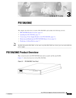
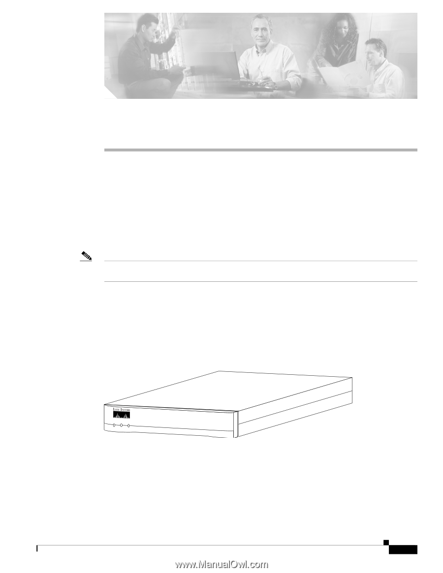
This section describes the PIX 506/506E front and rear panels and the panel LEDs.
Figure 3-1
shows the front view of the PIX 506/506E.
Figure 3-1
PIX 506/506E
Front Panel
67945
POWER
ACT
NETWORK
CISCO
PIX 506E
F
I
R
E
W
A
L
L