Cisco PIX 506E User Guide - Page 5
Connecting the Power Supply Module to the PIX 506 6-Pin Connector, Pin Connector, Step 1
 |
UPC - 746320661315
View all Cisco PIX 506E manuals
Add to My Manuals
Save this manual to your list of manuals |
Page 5 highlights
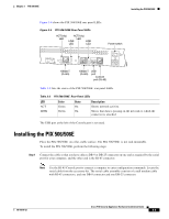
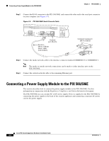
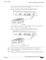
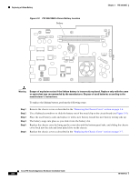
Chapter 3 PIX 506/506E Connecting a Power Supply Module to the PIX 506/506E Figure 3-6 displays the cable connection from the power supply to the PIX 506, and displays the AC power cord connector (at the opposite end of the power supply). Figure 3-6 Connecting the Power Supply Module to the PIX 506 6-Pin Connector ACT LINK ETHERNET 1 ACT LINK ETHERNET 0 USB CONSOLE DC POWER INPUT 38854 Power supply Figure 3-7 displays the cable connection from the power supply to the PIX 506E, and displays the AC power cord connector (at the opposite end of the power supply). Figure 3-7 Connecting the Power Supply Module to the PIX 506E 8-Pin Connector ACT LINK ETHERNET 1 ACT LINK ETHERNET 0 USB CONSOLE DC POWER INPUT 67847 Power supply Complete these steps to connect the power supply module: Step 1 Step 2 Step 3 Place the PIX 506/506E on a flat, stable surface. The PIX 506/506E is not rack mountable. Connect the power supply to the back of the PIX 506/506E. See Figure 3-6 for the PIX 506 and Figure 3-7 for the PIX 506E. When you are ready to start the PIX 506/506E, power on the unit from the switch at the rear of the unit. 78-15170-02 Cisco PIX Security Appliance Hardware Installation Guide 3-5
-
 1
1 -
 2
2 -
 3
3 -
 4
4 -
 5
5 -
 6
6 -
 7
7 -
 8
8
 |
 |
