Cisco WS-X4232 Hardware Maintenance Manual - Page 48
product meets the Class 1 Laser Emission Requirement from CDRH FDDI.
 |
UPC - 746320172057
View all Cisco WS-X4232 manuals
Add to My Manuals
Save this manual to your list of manuals |
Page 48 highlights
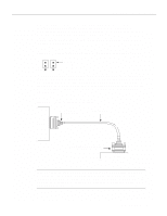
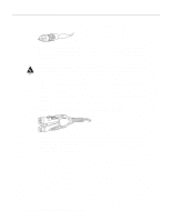
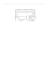
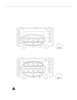
H1348a Network Connection Considerations Figure 2-25 Single-Mode FDDI Network Interface Connectors, FC Type The single-mode transmitter uses a small laser to transmit the light signal to the ring. Keep the transmit port covered whenever a cable is not connected to it. Although multimode transceivers typically use LEDs (not lasers) for transmission, keep open ports covered and avoid staring into open ports or apertures. Warning Invisible laser radiation may be emitted from the aperture ports of the single-mode FDDI products when no fiber cable is connected. Avoid exposure and do not stare into open apertures. This product meets the Class 1 Laser Emission Requirement from CDRH FDDI. The multimode network processor module connectors are FDDI-standard physical sublayer (PHY) connectors. The media interface connector (MIC) connects to FDDI standard 62.5/125 micron multimode fiber-optic cable. Figure 2-26 shows the MIC typically used for network and chassis connections in multimode FDDI applications. Figure 2-26 Multimode FDDI Network Interface Connector, MIC Type A dual-attachment module configuration requires two connections: one to the primary ring and one to the secondary ring. The PHY-A port is the bottom port (see Figure 2-24 and Figure 2-27), and PHY-B is the top port on both the multimode and single-mode modules. To connect to another dual-attachment station, connect PHY-A on the module to PHY-B on the other DAS and PHY-B on the module to PHY-A on the other DAS. 2-26 Cisco 4000 Series Hardware Installation and Maintenance H1349a
-
 1
1 -
2
-
3
-
4
-
5
-
6
-
7
-
8
-
9
-
10
-
11
-
12
-
13
-
14
-
15
-
16
-
17
-
18
-
19
-
20
-
21
-
22
-
23
-
24
-
25
-
26
-
27
-
28
-
29
-
30
-
31
-
32
-
33
-
34
-
35
-
36
-
37
-
38
-
39
-
40
-
41
-
42
-
 43
43 -
 44
44 -
 45
45 -
 46
46 -
 47
47 -
 48
48 -
 49
49 -
 50
50 -
 51
51 -
 52
52 -
 53
53 -
54
-
55
-
56
-
57
-
58
-
59
-
60
-
61
-
62
-
63
-
64
-
65
-
66
-
67
-
68
-
69
-
70
-
71
-
72
-
73
-
74
-
75
-
76
-
77
-
78
-
79
-
80
-
81
-
82
-
83
-
84
-
85
-
86
-
87
-
88
-
89
-
90
-
91
-
92
-
93
-
94
-
95
-
96
-
97
-
98
-
99
-
100
-
101
-
102
-
103
-
104
-
105
-
106
-
107
-
108
-
109
-
110
-
111
-
112
-
113
-
114
-
115
-
116
-
117
-
118
-
119
-
120
-
121
-
122
-
123
-
124
-
125
-
126
-
127
-
128
-
129
-
130
-
131
-
132
-
133
-
134
-
135
-
136
-
137
-
138
-
139
-
140
-
141
-
142
-
143
 |
 |
