Compaq Presario V5000 Compaq Presario V5000 Notebook PC - Maintenance and Serv - Page 117
Remove the two Phillips PM2.5×13.0 screws, that secure
 |
View all Compaq Presario V5000 manuals
Add to My Manuals
Save this manual to your list of manuals |
Page 117 highlights
Removal and Replacement Procedures ✎ Before disconnecting the antenna cables, make note of which cable is attached to which antenna clip on the Mini Card communications card. 3. Disconnect the auxiliary and main wireless antenna cables 1 from the Mini Card module. 4. Remove the two Phillips PM2.5×13.0 screws 2 that secure the display assembly to the computer. Disconnecting the Wireless Antenna Cables and Removing the Display Screws Maintenance and Service Guide 5-27
-
 1
1 -
2
-
3
-
4
-
5
-
6
-
7
-
8
-
9
-
10
-
11
-
12
-
13
-
14
-
15
-
16
-
17
-
18
-
19
-
20
-
21
-
22
-
23
-
24
-
25
-
26
-
27
-
28
-
29
-
30
-
31
-
32
-
33
-
34
-
35
-
36
-
37
-
38
-
39
-
40
-
41
-
42
-
43
-
44
-
45
-
46
-
47
-
48
-
49
-
50
-
51
-
52
-
53
-
54
-
55
-
56
-
57
-
58
-
59
-
60
-
61
-
62
-
63
-
64
-
65
-
66
-
67
-
68
-
69
-
70
-
71
-
72
-
73
-
74
-
75
-
76
-
77
-
78
-
79
-
80
-
81
-
82
-
83
-
84
-
85
-
86
-
87
-
88
-
89
-
90
-
91
-
92
-
93
-
94
-
95
-
96
-
97
-
98
-
99
-
100
-
101
-
102
-
103
-
104
-
105
-
106
-
107
-
108
-
109
-
110
-
111
-
 112
112 -
 113
113 -
 114
114 -
 115
115 -
 116
116 -
 117
117 -
 118
118 -
 119
119 -
 120
120 -
 121
121 -
 122
122 -
123
-
124
-
125
-
126
-
127
-
128
-
129
-
130
-
131
-
132
-
133
-
134
-
135
-
136
-
137
-
138
-
139
-
140
-
141
-
142
-
143
-
144
-
145
-
146
-
147
-
148
-
149
-
150
-
151
-
152
-
153
-
154
-
155
-
156
-
157
-
158
-
159
-
160
-
161
-
162
-
163
-
164
-
165
-
166
-
167
-
168
-
169
-
170
-
171
-
172
-
173
-
174
-
175
-
176
-
177
-
178
-
179
-
180
-
181
-
182
-
183
-
184
-
185
-
186
-
187
-
188
-
189
-
190
-
191
-
192
-
193
-
194
-
195
-
196
-
197
-
198
-
199
-
200
-
201
-
202
-
203
-
204
-
205
-
206
-
207
-
208
-
209
-
210
-
211
-
212
-
213
-
214
-
215
-
216
-
217
-
218
-
219
-
220
-
221
-
222
-
223
-
224
-
225
-
226
-
227
-
228
-
229
-
230
-
231
-
232
-
233
-
234
-
235
-
236
-
237
-
238
-
239
-
240
-
241
-
242
 |
 |

Removal and Replacement Procedures
Maintenance and Service Guide
5–27
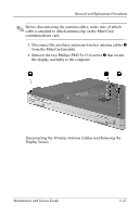
✎
Before disconnecting the antenna cables, make note of which
cable is attached to which antenna clip on the Mini Card
communications card.
3. Disconnect the auxiliary and main wireless antenna cables
1
from the Mini Card module.
4. Remove the two Phillips PM2.5×13.0 screws
2
that secure
the display assembly to the computer.
Disconnecting the Wireless Antenna Cables and Removing the
Display Screws