Compaq Presario V5000 Compaq Presario V5000 Notebook PC - Maintenance and Serv - Page 137
System Board, System Board Spare Part Number Information
 |
View all Compaq Presario V5000 manuals
Add to My Manuals
Save this manual to your list of manuals |
Page 137 highlights
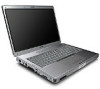
Removal and Replacement Procedures 5.15 System Board System Board Spare Part Number Information 945GM system board 407759-001 ✎ When replacing the system board, ensure that the following components are removed from the defective system board and installed on the replacement system board: ■ Memory modules (Section 5.6) ■ Mini Card communications module (Section 5.7) ■ RTC battery (Section 5.8) ■ Power connector cable (Section 5.15) ■ Heat sink (Section 5.18) ■ Processor (Section 5.19) ■ Fan/heat sink assembly (Section 5.18) ■ PC Card assembly (Section 5.20) 1. Prepare the computer for disassembly (Section 5.3), and then remove the following components: a. Hard drive (Section 5.4) b. Memory/Mini Card module compartment cover (Section 5.6) c. Optical drive (Section 5.9) d. Switch cover (Section 5.10) e. Keyboard (Section 5.11) f. Display assembly (Section 5.12) g. Base enclosure (Section 5.13) 2. Turn the top cover right-side up with the front toward you. Maintenance and Service Guide 5-47
-
 1
1 -
2
-
3
-
4
-
5
-
6
-
7
-
8
-
9
-
10
-
11
-
12
-
13
-
14
-
15
-
16
-
17
-
18
-
19
-
20
-
21
-
22
-
23
-
24
-
25
-
26
-
27
-
28
-
29
-
30
-
31
-
32
-
33
-
34
-
35
-
36
-
37
-
38
-
39
-
40
-
41
-
42
-
43
-
44
-
45
-
46
-
47
-
48
-
49
-
50
-
51
-
52
-
53
-
54
-
55
-
56
-
57
-
58
-
59
-
60
-
61
-
62
-
63
-
64
-
65
-
66
-
67
-
68
-
69
-
70
-
71
-
72
-
73
-
74
-
75
-
76
-
77
-
78
-
79
-
80
-
81
-
82
-
83
-
84
-
85
-
86
-
87
-
88
-
89
-
90
-
91
-
92
-
93
-
94
-
95
-
96
-
97
-
98
-
99
-
100
-
101
-
102
-
103
-
104
-
105
-
106
-
107
-
108
-
109
-
110
-
111
-
112
-
113
-
114
-
115
-
116
-
117
-
118
-
119
-
120
-
121
-
122
-
123
-
124
-
125
-
126
-
127
-
128
-
129
-
130
-
131
-
 132
132 -
 133
133 -
 134
134 -
 135
135 -
 136
136 -
 137
137 -
 138
138 -
 139
139 -
 140
140 -
 141
141 -
 142
142 -
143
-
144
-
145
-
146
-
147
-
148
-
149
-
150
-
151
-
152
-
153
-
154
-
155
-
156
-
157
-
158
-
159
-
160
-
161
-
162
-
163
-
164
-
165
-
166
-
167
-
168
-
169
-
170
-
171
-
172
-
173
-
174
-
175
-
176
-
177
-
178
-
179
-
180
-
181
-
182
-
183
-
184
-
185
-
186
-
187
-
188
-
189
-
190
-
191
-
192
-
193
-
194
-
195
-
196
-
197
-
198
-
199
-
200
-
201
-
202
-
203
-
204
-
205
-
206
-
207
-
208
-
209
-
210
-
211
-
212
-
213
-
214
-
215
-
216
-
217
-
218
-
219
-
220
-
221
-
222
-
223
-
224
-
225
-
226
-
227
-
228
-
229
-
230
-
231
-
232
-
233
-
234
-
235
-
236
-
237
-
238
-
239
-
240
-
241
-
242
 |
 |
