Craftsman 17540 Operation Manual - Page 19
DEPTH-STOP, RODANDDEPTH-STOP, TURRET, 7andS, TheDepth-Stop, Rodand, theDepth-Stop, Turret, areused,
 |
View all Craftsman 17540 manuals
Add to My Manuals
Save this manual to your list of manuals |
Page 19 highlights
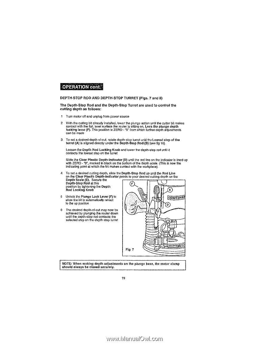
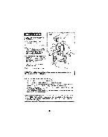
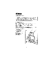
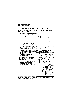
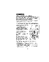
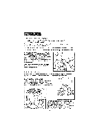
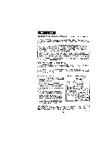
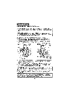
DEPTH-STROOPDANDDEPTH-STTOUPRRE(FTigs7,,andS) TheDepth-StRopodandtheDepth-StTouprreatreusedtocontrothl e cuttingdepthasfollows: t Turn motor off and unplug from power source 2 With the cutting bit already installed,Iowar the plunge action until the cutter bit makes contact with the f_at,level surface the router is sitting on, Lock the plunge depth locking lever (F}oThis position is ZERO - "0" lrom which furtherdepth adjustments can be made 3 To set a desired depth-el-cut, rotate depth-stop turret until theLowest step of the turret (A) is aligned dlreegy under the Depth*Stop Rod (B) (see I]g 10), Loosen the Depth Rod Locking Knob and lower the depth-stop rod until it contactsthe lowest step on the turret Slide the Clear Plastic Depth-tndlcstor (D) until the red line on the indicator is lined up with ZERO - "0", marked in black on the bottom of the depth scale, (Thls is now the indicating point at which the bit makes contact wi|h the workpiece) To set a desired cutting depth, slide the Depth-Stop Rod up until lhe Red Line on the Clear Plastic Depth-indicator points to your desired curling dep|h on Ihe Depth Scale (E), Secure the Depth-Stop Rod st thls (_ position by tighleniog the Depth Rod Locking Knob 5 Unlock the Plunge Lock Lever (F) to allow the bit to automatically retract to the up position The desired depth-of-cut may now be achieved by plunging the router down unltt the depth-stop rod conlacts the selected step en the depth-stop turret Fig- 7 "1 ! sNhOoTuEld,' Walhweanysmabkeincg!osdeedptshecaudrjueslyt.ments on the plunge base_ the motor clamp | 19
-
 1
1 -
2
-
3
-
4
-
5
-
6
-
7
-
8
-
9
-
10
-
11
-
12
-
13
-
 14
14 -
 15
15 -
 16
16 -
 17
17 -
 18
18 -
 19
19 -
 20
20 -
 21
21 -
 22
22 -
 23
23 -
 24
24 -
25
-
26
-
27
-
28
-
29
-
30
-
31
-
32
-
33
-
34
-
35
-
36
-
37
-
38
-
39
-
40
 |
 |