Craftsman 21914 Operation Manual - Page 22
Changingspeeds
 |
View all Craftsman 21914 manuals
Add to My Manuals
Save this manual to your list of manuals |
Page 22 highlights
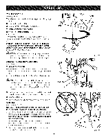
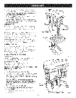
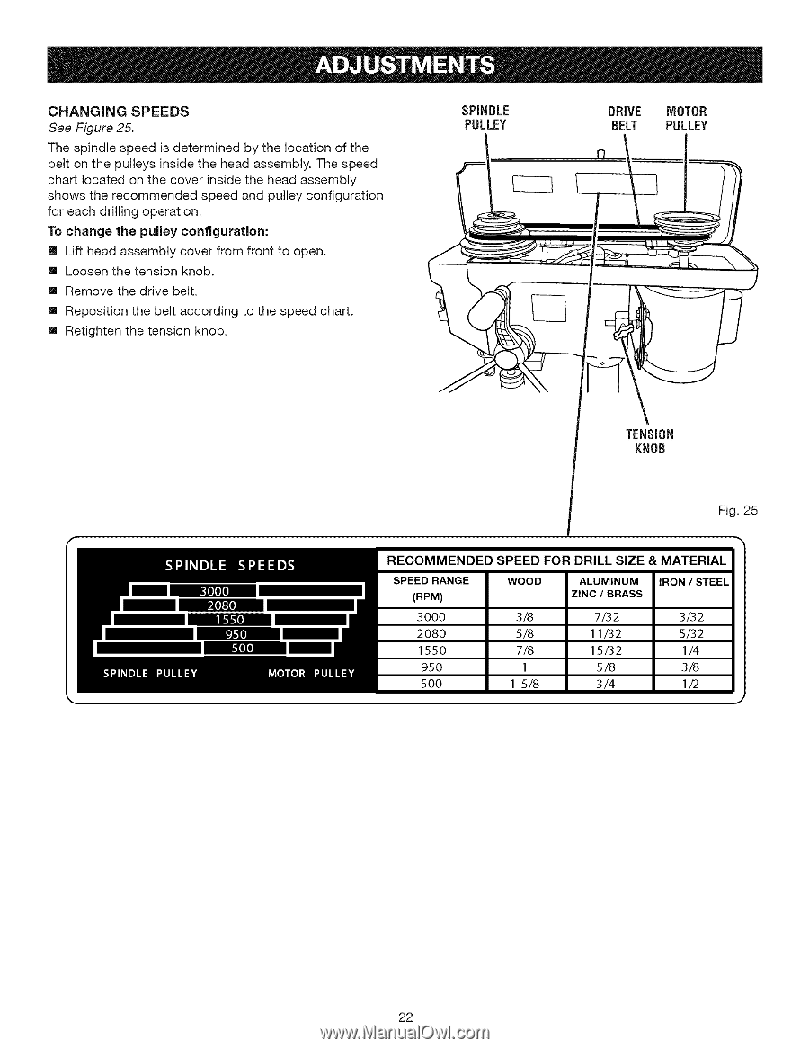
CHANGINGSPEEDS See Figure 25. The spindle speed is determined by the location of the belt on the pulleys inside the head assembly. The speed chart located on the cover inside the head assembly shows the recommended speed and pulley configuration for each drilling operation. To change the pulley configuration: [] Lift head assembly cover from front to open. [] Loosen the tension knob. [] Remove the drive belt. [] Reposition the belt according to the speed chart. [] Retighten the tension knob. SPINDLE PULLEY DRIVE MOTOR BELT PULLEY TENSION KNOB Fig. 25 22
-
 1
1 -
2
-
3
-
4
-
5
-
6
-
7
-
8
-
9
-
10
-
11
-
12
-
13
-
14
-
15
-
16
-
 17
17 -
 18
18 -
 19
19 -
 20
20 -
 21
21 -
 22
22 -
 23
23 -
 24
24 -
 25
25
 |
 |
CHANGINGSPEEDS
See Figure 25.
The spindle speed is determined
by the location
of the
belt on the pulleys inside the head assembly. The speed
chart located on the cover inside the head assembly
shows the recommended
speed and pulley configuration
for each drilling operation.
To
change
the
pulley configuration:
[]
Lift head assembly
cover from front to open.
[]
Loosen the tension
knob.
[]
Remove the drive belt.
[]
Reposition
the belt according
to the speed chart.
[]
Retighten the tension
knob.
SPINDLE
DRIVE
MOTOR
PULLEY
BELT
PULLEY
TENSION
KNOB
Fig. 25
22