Cub Cadet Z-Force 48 Z-Force 48 Operator's Manual - Page 27
Adjustments - inch mower
 |
View all Cub Cadet Z-Force 48 manuals
Add to My Manuals
Save this manual to your list of manuals |
Page 27 highlights
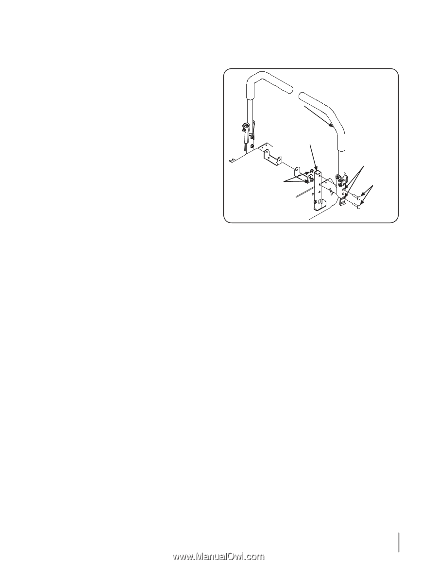
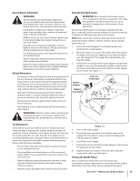
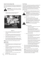
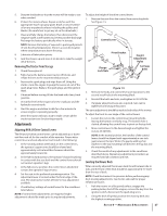
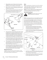
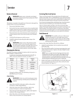
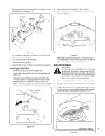
5. Sharpen the blades so that the mower will be ready to use when needed. 6. Protect the metal surfaces. Repair scratches with the appropriate touch-up spray paint. Brush a rust preventive oil on any unpainted surfaces including the pulleys and blades. (Be careful not to get any oil on the drive belts.) 7. Clean and fully charge the battery, then disconnect the negative cable at the battery to prevent possible discharge. Recharge the battery periodically when in storage. NOTE: Remove the battery if exposed to prolonged periods of sub-freezing temperatures. Store in a cool, dry location where temperatures are above freezing. 8. Lubricate all lubrication points. 9. Jack the mower up and store it on blocks to take the weight off of the tires. Removing The Tractor From Storage 1. Check the engine oil. 2. Fully charge the battery, lower tractor off blocks, and inflate the tires to the recommended pressure. 3. Remove the spark plugs and wipe them off. Using the starter, crank the engine to pump the excess oil out of the spark plug holes. Replace the spark plugs and the ignition leads. 4. If drained before storing, fill the fuel tank with clean, fresh gasoline. 5. Check the level of the engine oil in the crankcase and the hydraulic reservoir tank. 6. Start the engine and allow to idle for a few minutes to ensure engine is operating properly. 7. Drive the tractor without a load to make certain all the tractor systems are functioning properly. Adjustments Adjusting RH & LH Drive Control Levers The RH and LH drive control levers can be adjusted up or down and fore-and-aft for the comfort of the operator. Proper drive control lever and seat adjustment will result in the following: 1. In the neutral position with hands on the control levers, the operator's upper arms should be relaxed and approximately vertical and their forearms should be approximately horizontal. 2. In the full forward position, the operator's back should stay in contact with the seat back and the control levers should not contact operator's legs. 3. In the full reverse position, the control levers should not contact the operator's legs or torso. 4. Set the seat to the preferred operating position. The adjustment lever is located under the front edge of the seat. The seat has five inches of front-to-rear adjustment available. 5. Check factory settings of control levers for the conditions listed above. NOTE: If control lever adjustments are required, height adjustments should be made prior to angular adjustments. To adjust the height of the drive control levers: 1. Remove the nuts from the control lever mounting bolts. See Figure 1-5. Control Lever Pivot Bracket Flange Lock Nuts Height Adjustment Holes Carriage Bolts Figure 1-5 2. Remove the bolts and control lever and reposition to the second set of holes in the mounting block. 3. Reinstall the bolts and nuts, and tighten to 28-34 ft-lbs. 4. If angular adjustments are also required, nuts can be tightened until snug at this point. The same adjustments should be made to both sides of the mower. To adjust the front-to-rear angle of the control levers: 1. Loosen the nuts on the control lever mounting bolts, leaving the bottom one fairly snug. The bottom hole is slotted, allowing the control lever to pivot on the top bolt. 2. Move control lever to the desired angle and tighten the nuts to 28-34 ft-lbs. NOTE: In the neutral position, the handles of the control levers should be aligned with approximately a one inch gap between the tips. Widen the gap by adding shim washers to the top mounting bolt between the lap bar and the mounting block. 3. Check the results of any adjustments to the conditions described above. Repeat any adjustment procedures as required until all conditions are met. Leveling the Mower Deck When correctly adjusted the mower deck should be level side to side, and the front of the deck should be approximately 1⁄4" lower than the rear of deck. NOTE: Check the tractor's tire pressure before performing any deck leveling adjustments. See the tire side wall for proper inflation pressures. 1. Park the mower on a flat paved surface, engage the parking brake, shut off the engine, remove the key from the ignition switch, disconnect the spark plug wires. 2. Using the deck lift pedal, position the mowing deck into the highest mowing position. Section 6 - Maintenance & Adjustments 27
-
 1
1 -
2
-
3
-
4
-
5
-
6
-
7
-
8
-
9
-
10
-
11
-
12
-
13
-
14
-
15
-
16
-
17
-
18
-
19
-
20
-
21
-
 22
22 -
 23
23 -
 24
24 -
 25
25 -
 26
26 -
 27
27 -
 28
28 -
 29
29 -
 30
30 -
 31
31 -
 32
32 -
33
-
34
-
35
-
36
-
37
-
38
-
39
-
40
 |
 |