D-Link DGS-3100-48P Product Manual - Page 94
Defining VLAN Trunking - switch 48
 |
UPC - 790069304781
View all D-Link DGS-3100-48P manuals
Add to My Manuals
Save this manual to your list of manuals |
Page 94 highlights
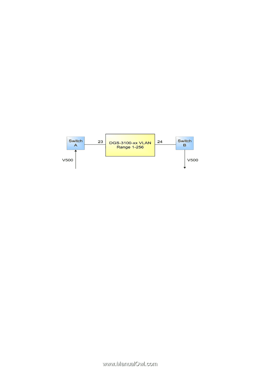
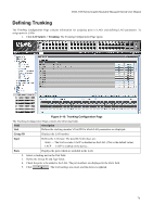
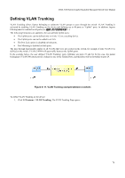
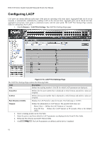
DGS-3100 Series Gigabit Stackable Managed Switch User Manual Defining VLAN Trunking VLAN Trunking allows frames belonging to unknown VLAN groups to pass through the switch. VLAN Trunking is activated by enabling VLAN Trunking on the device and defining up to 48 ports as "Uplink" ports. In addition, Ingress Filtering must be enabled on all ports (see The following limitations are applied to the user-defined Uplink ports: • The Uplink ports can be defined only on Units 1-2 on a stacking device. • The Uplink ports can not be added to a LAG. • The Port Lock option is disabled on both ports. • Port Mirroring is disabled on both ports. The pass through functionality applies to all VLANs that were not created on the switch, for example if only VLAN #1 is defined on the switch, VLANs 2-4094 will pass traffic between the Uplink ports. In the example below, the user defined 'VLAN Trunking' ports (Uplinks) are ports 23 and 24. In this case, the packet belonging to VLAN 500 enters port 23, defined as one of the Uplink Ports, and therefore will be forwarded to port 24. Figure 0-11. VLAN Trunking example between 2 switchs To define VLAN Trunking on the device: 1. Click L2 Features > VLAN Trunking. The VLAN Trunking Page opens: 78
-
 1
1 -
2
-
3
-
4
-
5
-
6
-
7
-
8
-
9
-
10
-
11
-
12
-
13
-
14
-
15
-
16
-
17
-
18
-
19
-
20
-
21
-
22
-
23
-
24
-
25
-
26
-
27
-
28
-
29
-
30
-
31
-
32
-
33
-
34
-
35
-
36
-
37
-
38
-
39
-
40
-
41
-
42
-
43
-
44
-
45
-
46
-
47
-
48
-
49
-
50
-
51
-
52
-
53
-
54
-
55
-
56
-
57
-
58
-
59
-
60
-
61
-
62
-
63
-
64
-
65
-
66
-
67
-
68
-
69
-
70
-
71
-
72
-
73
-
74
-
75
-
76
-
77
-
78
-
79
-
80
-
81
-
82
-
83
-
84
-
85
-
86
-
87
-
88
-
 89
89 -
 90
90 -
 91
91 -
 92
92 -
 93
93 -
 94
94 -
 95
95 -
 96
96 -
 97
97 -
 98
98 -
 99
99 -
100
-
101
-
102
-
103
-
104
-
105
-
106
-
107
-
108
-
109
-
110
-
111
-
112
-
113
-
114
-
115
-
116
-
117
-
118
-
119
-
120
-
121
-
122
-
123
-
124
-
125
-
126
-
127
-
128
-
129
-
130
-
131
-
132
-
133
-
134
-
135
-
136
-
137
-
138
-
139
-
140
-
141
-
142
-
143
-
144
-
145
-
146
-
147
-
148
-
149
-
150
-
151
-
152
-
153
-
154
-
155
-
156
-
157
-
158
-
159
-
160
-
161
-
162
-
163
-
164
-
165
-
166
-
167
-
168
-
169
-
170
-
171
-
172
-
173
-
174
-
175
-
176
-
177
-
178
-
179
-
180
-
181
-
182
-
183
-
184
-
185
-
186
-
187
-
188
-
189
-
190
-
191
-
192
-
193
-
194
-
195
-
196
-
197
-
198
-
199
-
200
-
201
-
202
-
203
-
204
-
205
-
206
-
207
-
208
-
209
-
210
-
211
-
212
-
213
-
214
-
215
-
216
-
217
-
218
-
219
-
220
-
221
-
222
-
223
-
224
-
225
-
226
-
227
-
228
-
229
-
230
-
231
-
232
-
233
-
234
-
235
-
236
-
237
-
238
-
239
-
240
-
241
-
242
-
243
-
244
-
245
-
246
-
247
-
248
-
249
-
250
-
251
-
252
-
253
-
254
-
255
-
256
-
257
-
258
-
259
-
260
-
261
-
262
-
263
-
264
-
265
-
266
-
267
-
268
-
269
-
270
-
271
-
272
-
273
-
274
-
275
-
276
-
277
-
278
-
279
-
280
-
281
-
282
-
283
-
284
-
285
-
286
-
287
-
288
-
289
-
290
-
291
-
292
-
293
 |
 |