D-Link DGS-6600-48T Hardware Installation Guide - Page 18
DGS-6608 Product Appearance, Number, Item Name, Description
 |
View all D-Link DGS-6600-48T manuals
Add to My Manuals
Save this manual to your list of manuals |
Page 18 highlights
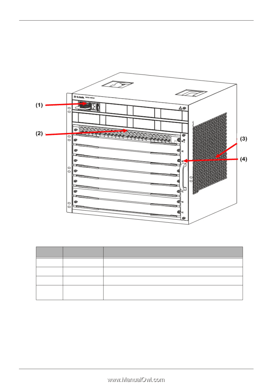
DGS-6600 Layer 3 Chassis Ethernet Managed Switch Hardware Installation Guide DGS-6608 Product Appearance Figure 1-3 DGS-6608 Product Appearance Number 1 2 3 4 Item Name Description Power Layer The built-in power shelf can host up to eight power modules. Module Layer Air Outlet Fan Tray The module layer offers 8 module slots. The air outlet is located on the right side of the Switch. The fan tray is installed in the slot on the right side of the Switch. The fan tray is the Switch's main heat dissipation unit. Table 1-2 DGS-6608 Product Appearance Descriptions 7
-
 1
1 -
2
-
3
-
4
-
5
-
6
-
7
-
8
-
9
-
10
-
11
-
12
-
 13
13 -
 14
14 -
 15
15 -
 16
16 -
 17
17 -
 18
18 -
 19
19 -
 20
20 -
 21
21 -
 22
22 -
 23
23 -
24
-
25
-
26
-
27
-
28
-
29
-
30
-
31
-
32
-
33
-
34
-
35
-
36
-
37
-
38
-
39
-
40
-
41
-
42
-
43
-
44
-
45
-
46
-
47
-
48
-
49
-
50
-
51
-
52
-
53
-
54
-
55
-
56
-
57
-
58
-
59
-
60
-
61
-
62
-
63
-
64
-
65
-
66
-
67
-
68
-
69
-
70
-
71
-
72
-
73
-
74
-
75
-
76
-
77
-
78
-
79
-
80
-
81
-
82
-
83
-
84
-
85
-
86
-
87
-
88
-
89
-
90
-
91
-
92
-
93
-
94
-
95
-
96
 |
 |
DGS-6600 Layer 3 Chassis Ethernet Managed Switch Hardware Installation Guide
7
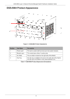
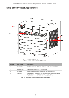
DGS-6608 Product Appearance
Figure 1-3 DGS-6608 Product Appearance
Number
Item Name
Description
1
Power Layer
The built-in power shelf can host up to eight power modules.
2
Module Layer
The module layer offers 8 module slots.
3
Air Outlet
The air outlet is located on the right side of the Switch.
4
Fan Tray
The fan tray is installed in the slot on the right side of the Switch.
The fan tray is the Switch’s main heat dissipation unit.
Table 1-2 DGS-6608 Product Appearance Descriptions