D-Link DGS-6600-48T Hardware Installation Guide - Page 45
Ventilation Requirements, Schematic Diagram for the ventilation of the DGS-6604
 |
View all D-Link DGS-6600-48T manuals
Add to My Manuals
Save this manual to your list of manuals |
Page 45 highlights
DGS-6600 Layer 3 Chassis Ethernet Managed Switch Hardware Installation Guide Ventilation Requirements Figure 2-1 shows the ventilation requirements of the DGS-6604 and Figure 2-2 shows the vent alation requirements of the DGS-6608. To ensure normal ventilation, please allow sufficient space at the ventilation openings of the DGS-6600 series switch. After connecting cables to the DGS-6600 series switch, ensure that the cables are arranged in bundles and are positioned so that they don't block the Switch's air inlets. Figure 2-1 Schematic Diagram for the ventilation of the DGS-6604 6 7 8 Figure 2-2 Schematic Diagram for the ventilation of the DGS-6608 34
-
 1
1 -
2
-
3
-
4
-
5
-
6
-
7
-
8
-
9
-
10
-
11
-
12
-
13
-
14
-
15
-
16
-
17
-
18
-
19
-
20
-
21
-
22
-
23
-
24
-
25
-
26
-
27
-
28
-
29
-
30
-
31
-
32
-
33
-
34
-
35
-
36
-
37
-
38
-
39
-
 40
40 -
 41
41 -
 42
42 -
 43
43 -
 44
44 -
 45
45 -
 46
46 -
 47
47 -
 48
48 -
 49
49 -
 50
50 -
51
-
52
-
53
-
54
-
55
-
56
-
57
-
58
-
59
-
60
-
61
-
62
-
63
-
64
-
65
-
66
-
67
-
68
-
69
-
70
-
71
-
72
-
73
-
74
-
75
-
76
-
77
-
78
-
79
-
80
-
81
-
82
-
83
-
84
-
85
-
86
-
87
-
88
-
89
-
90
-
91
-
92
-
93
-
94
-
95
-
96
 |
 |
DGS-6600 Layer 3 Chassis Ethernet Managed Switch Hardware Installation Guide
34
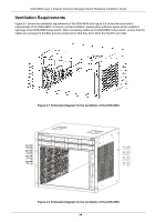
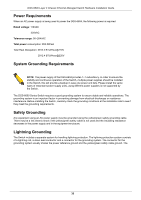
Ventilation Requirements
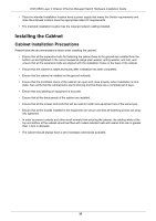
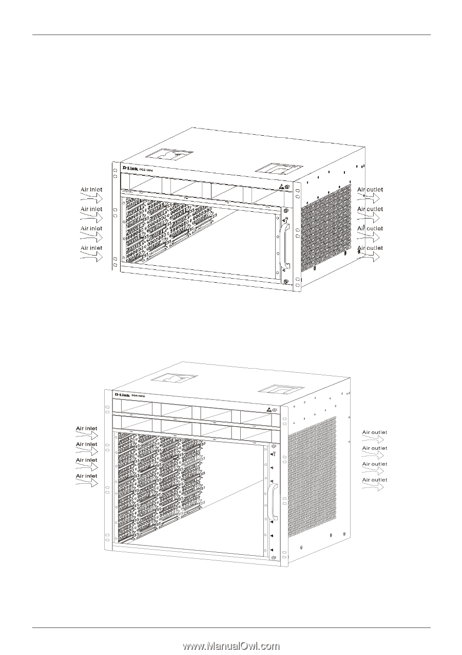
Figure 2-1 shows the ventilation requirements of the DGS-6604 and Figure 2-2 shows the vent alation
requirements of the DGS-6608. To ensure normal ventilation, please allow sufficient space at the ventilation
openings of the DGS-6600 series switch. After connecting cables to the DGS-6600 series switch, ensure that the
cables are arranged in bundles and are positioned so that they don’t block the Switch's air inlets.
Figure 2-1 Schematic Diagram for the ventilation of the DGS-6604
Figure 2-2 Schematic Diagram for the ventilation of the DGS-6608
6
7
8