D-Link DSN-3400-10 Hardware Reference Guide for DSN-3200-10 Valid for fir
D-Link DSN-3400-10 - xStack Storage Area Network Array Hard Drive Manual
 |
UPC - 790069299766
View all D-Link DSN-3400-10 manuals
Add to My Manuals
Save this manual to your list of manuals |
D-Link DSN-3400-10 manual content summary:
- D-Link DSN-3400-10 | Hardware Reference Guide for DSN-3200-10
Valid for fir - Page 1
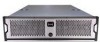
xStack Storage TM D-Link xStack Storage iSCSI SAN Array Managed SAN Solution DSN-3200 & DSN-3400 Hardware Reference Guide Version 1.0 - D-Link DSN-3400-10 | Hardware Reference Guide for DSN-3200-10
Valid for fir - Page 2
warranty statements accompanying such products and services. Nothing herein should be construed as constituting an additional warranty. D-Link shall not be liable for technical or editorial errors or omissions contained herein. Copyright © 2008 D-Link Systems, Inc.™ Trademarks Adobe® and Acrobat - D-Link DSN-3400-10 | Hardware Reference Guide for DSN-3200-10
Valid for fir - Page 3
need to replace it. However, should you need to replace it, consult your service documentation. Do not dispose of the battery along with household waste. Contact your government. Please contact D-Link Systems, Inc. for any export compliance questions. DSN-3000 series Hardware Reference Guide iii - D-Link DSN-3400-10 | Hardware Reference Guide for DSN-3200-10
Valid for fir - Page 4
Document Revision Level Revision Date Version 1.0 October 10, 2008 Notes iv - D-Link DSN-3400-10 | Hardware Reference Guide for DSN-3200-10
Valid for fir - Page 5
to assist users with installing the xStack Storage system from DLink. This document assumes that users are computer literate, familiar the following documents are available from D-Link. xStack Storage Management Center Software User's Guide. This guide provides the information needed to configure - D-Link DSN-3400-10 | Hardware Reference Guide for DSN-3200-10
Valid for fir - Page 6
to Friday 8:00am - 5:00pm PST/PDT D-Link Technical Support over the Internet: http://support.dlink.com Tech Support for customers within Canada: D-Link Technical Support over the Telephone Please see our support site for current number: http://support.dlink.ca Monday to Friday 7:30am to 9:00pm - D-Link DSN-3400-10 | Hardware Reference Guide for DSN-3200-10
Valid for fir - Page 7
...9 1.1 Model 9 1.2 Benefits and Features 10 1.3 System Overview 10 Chapter 2 DSN-3000 series Layout ...11 2.1 Front Panel Components Ports 25 3.4.1 Connecting to the DSN-3200 Host Network Connection Ports 25 3.4.2 Connecting to the DSN-3400 Host Network Connection Port 25 3.5 Connecting - D-Link DSN-3400-10 | Hardware Reference Guide for DSN-3200-10
Valid for fir - Page 8
This Page Left Intentionally Blank viii Contents - D-Link DSN-3400-10 | Hardware Reference Guide for DSN-3200-10
Valid for fir - Page 9
DSN-3200) or one 10GbE connection (DSN-3400) accessed via the back panel A 10/100 Mbps management port An RS-232-C DB9 diagnostic port for troubleshooting about supported drives, consult the Interoperability Matrix found on the D-Link Support Web site: support.dlink.com 1.1 Model The DSN-3000 - D-Link DSN-3400-10 | Hardware Reference Guide for DSN-3200-10
Valid for fir - Page 10
by the servers exchanging data with the DSN-3000 series storage system can be very high. Using a separate Ethernet to act as a SAN keeps that data from interfering with the customer's existing LAN and improves security. Figure 1-1 DSN-3000 Series Storage System Diagram 10 Chapter 1 Introduction - D-Link DSN-3400-10 | Hardware Reference Guide for DSN-3200-10
Valid for fir - Page 11
This chapter describes the hardware components on the DSN-3000 series storage system. The topics covered in this chapter are: Section 2.1, Front Panel Components Section 2.2, Back Panel Components Section 2.3, Side and Bottom Panel Components DSN-3000 series Hardware Reference Guide 11 - D-Link DSN-3400-10 | Hardware Reference Guide for DSN-3200-10
Valid for fir - Page 12
and Table 2-1) Boot and Fault LED - shows whether the DSN-3000 series is ready for operation or encountered a fault condition. (see /fault LEDs. (see Figure 2-1 and Table 2-2) Figure 2-1 Front View of the DSN-3000 Series Storage System When installed, the front bezel uses pipes to pass light from - D-Link DSN-3400-10 | Hardware Reference Guide for DSN-3200-10
Valid for fir - Page 13
Color Green Boot and Fault OFF Red Green Table 2-1. Front Panel LEDs Description ON = DSN-3000 series is powered on. OFF = power is not being received. Array is powered off SATA drive. Red ON Drive has experienced a fault and is offline DSN-3000 series Hardware Reference Guide 13 - D-Link DSN-3400-10 | Hardware Reference Guide for DSN-3200-10
Valid for fir - Page 14
ports. This requires a female-to-female straight-through cable provided with the system. (see Figure 2-4 for the DSN-3200 and Figure 2-6 for the DSN-3400) Management port (Mgmt 10/100) - one 10/100 RJ-45 management is located to the right of the diagnostic port. The management port has port speed - D-Link DSN-3400-10 | Hardware Reference Guide for DSN-3200-10
Valid for fir - Page 15
Array. Pressing this switch for longer than 3 seconds removes power from the xStack Storage Array and turns off the unit. Resets the xStack Storage Array. DSN-3000 series Hardware Reference Guide 15 - D-Link DSN-3400-10 | Hardware Reference Guide for DSN-3200-10
Valid for fir - Page 16
Table 2-4 Host Network Connection LED Indicators on the xStack DSN-3200 Enclosure LED Port Speed Color Yellow Port Activity Green Description ON = link is operating at 1 Gbps. OFF = link is operating at either 10 Mbps or 100 Mbps. ON = link is operational. Blink = data is being sent or received - D-Link DSN-3400-10 | Hardware Reference Guide for DSN-3200-10
Valid for fir - Page 17
Blinking Yellow OFF Yellow ON Description Link is operational. Data is being transmitted or received on the RJ-45 port. Connection has been established at 10 Mbps. Connection has been established at 100 Mbps. Figure 2-5 Management Port LED Locations DSN-3000 series Hardware Reference Guide 17 - D-Link DSN-3400-10 | Hardware Reference Guide for DSN-3200-10
Valid for fir - Page 18
Interfaces The back of the xStack DSN-3400 enclosure provides the following external interfaces: A single 10 GbE XFP transceiver host network the xStack DSN-3400 enclosure. Table 2-6 Host Network Connection LED Indicators on the xStack DSN-3400 Enclosure LED Tx Link Rx Link Color OFF Blinks - D-Link DSN-3400-10 | Hardware Reference Guide for DSN-3200-10
Valid for fir - Page 19
on the xStack DSN-3400 Enclosure LED Activity/Link Port Speed Color Green ON Green Blinking Yellow OFF Yellow ON OFF Yellow Meaning Link is operational. Data is being transmitted or received on the RJ-45 port. Connection has been established at 10 Mbps. Connection has been established at 100 Mbps - D-Link DSN-3400-10 | Hardware Reference Guide for DSN-3200-10
Valid for fir - Page 20
This Page Left Intentionally Blank 20 Chapter 2 DSN-3000 series Layout - D-Link DSN-3400-10 | Hardware Reference Guide for DSN-3200-10
Valid for fir - Page 21
in this chapter are: Section 3.1, Site Considerations Section3.2, Unpacking the DSN-3000 Series Storage System Section 3.3, Items Supplied by the User 3.6, Connecting the Power Cords Section 3.7, Powering-on the DSN-3000 series Storage System DSN-3000 series Hardware Reference Guide 21 - D-Link DSN-3400-10 | Hardware Reference Guide for DSN-3200-10
Valid for fir - Page 22
be mounted on a desktop or shelf. Observe the following considerations for desktop or shelf installations. Select a sturdy, level surface that can support the DSN-3000 series storage system. A fully populated unit weighs approximately 73 lbs. (33 kg.). Allow enough ventilation space between the - D-Link DSN-3400-10 | Hardware Reference Guide for DSN-3200-10
Valid for fir - Page 23
. Follow the instructions in the documentation for the rack. The operating ambient temperature of rack-mounted equipment must not exceed the maximum rated ambient temperature indicated in this guide. The rack cabinet must provide sufficient airflow to the front and back of the DSN-3000 series - D-Link DSN-3400-10 | Hardware Reference Guide for DSN-3200-10
Valid for fir - Page 24
to Perform the DSN-3000 series Storage System Installation User Category User-Supplied Items All Users DSN-3200 Users DSN-3400 Users A want to use the DSN-3000 series storage system's Link Aggregation feature, the switch must support LAGs. An IP address for each DSN-3200 storage system host - D-Link DSN-3400-10 | Hardware Reference Guide for DSN-3200-10
Valid for fir - Page 25
DSN-3200 storage system, follow the instructions in section 3.4.1. If you have the DSN3400 storage system, follow the instructions in section 3.4.2. 3.4.1 Connecting to the DSN-3200 Host Network Connection Ports The DSN DSN-3400 Host Network Connection Port The DSN-3400 storage system has a single 10 - D-Link DSN-3400-10 | Hardware Reference Guide for DSN-3200-10
Valid for fir - Page 26
a PC. 2. Connect the other end of the cable into the DSN-3000 series storage system Mgmt 10/100 port. This port is located to the right of the diagnostic port on the back panel (see Figure 2-4 for the DSN-3200 and Figure 2-6 for the DSN-3400). Do not connect one NIC to the management and host - D-Link DSN-3400-10 | Hardware Reference Guide for DSN-3200-10
Valid for fir - Page 27
storage system. The LED turns green when the startup process completes. If the LED turns red, reboot the DSN-3000 series storage system. If the problem persists, contact Technical Support. The message RCP sequence complete appears on the PC monitor. After verifying this message, disconnect the PC - D-Link DSN-3400-10 | Hardware Reference Guide for DSN-3200-10
Valid for fir - Page 28
This Page Left Intentionally Blank 28 Chapter 3 Installing the DSN-3000 series Storage System - D-Link DSN-3400-10 | Hardware Reference Guide for DSN-3200-10
Valid for fir - Page 29
pad. Make sure the battery cable and connector is located nearest to the battery socket J35 on the controller (see Figure A-1 ). Figure A-1 Aligning the Battery DSN-3000 series Hardware Reference Guide 29 - D-Link DSN-3400-10 | Hardware Reference Guide for DSN-3200-10
Valid for fir - Page 30
2. Press the battery down firmly as shown in Figure A-2 until you feel it lock into place. Figure A-2 Press the Battery Down Firmly Until it Locks 3. Align the battery plug with connector J35 as shown in Figure A-3 and insert it fully into the socket. Figure A-3 Align the Battery Plug with - D-Link DSN-3400-10 | Hardware Reference Guide for DSN-3200-10
Valid for fir - Page 31
4. The connector locked firmly into connector J35. Figure A-4 Battery Plug Locked in Place 5. The installed battery is shown in Figure A-5. Figure A-5 The Installed Battery DSN-3000 series Hardware Reference Guide 31 - D-Link DSN-3400-10 | Hardware Reference Guide for DSN-3200-10
Valid for fir - Page 32
be installed as matching pairs. Table A-1 lists the specifications for DIMMs supported by the xStack Storage Array. These memory module specifications are crucial to the operation of your SAN array. Please visit the www.dlink.com website for tested memory modules. Table A-2 shows the possible - D-Link DSN-3400-10 | Hardware Reference Guide for DSN-3200-10
Valid for fir - Page 33
at DDR333 speed. DIMMs must be organized as x72 bits wide, allowing support for ECC. DIMMs must use 8-bit wide DRAMs that can support data mask (DM) signals. DIMMs that use 4-bit-wide DRAMs do not 512MB 1GB 2GB 4GB Total Memory 1GB 1.5GB 2.5GB 4.5GB DSN-3000 series Hardware Reference Guide 33 - D-Link DSN-3400-10 | Hardware Reference Guide for DSN-3200-10
Valid for fir - Page 34
A.3 Installing or Replacing SATA Drives Removal of a populated drive/tray assembly can have unforeseen effects including the loss of all data in a volume. A drive can be part of a volume that may or may not be redundant. Before removing a drive from an operating xStack Storage Array, make sure it is - D-Link DSN-3400-10 | Hardware Reference Guide for DSN-3200-10
Valid for fir - Page 35
lifting the piece out of the tray as shown in Figure A-9. Figure A-9 Removing the Plastic Air Dam Piece 2. Your tray should now look like Figure A-10. Figure A-10 Tray with Air Dam Removed DSN-3000 series Hardware Reference Guide 35 - D-Link DSN-3400-10 | Hardware Reference Guide for DSN-3200-10
Valid for fir - Page 36
3. Place new hard drive in tray as shown in Figure A-11. Figure A-11 Place Hard Drive in Tray 4. Align the mounting holes and insert four mounting screws to hold the drive securely in the drive tray as shown in Figure A-12. Figure A-12 Secure the Hard Drive in the Drive Tray 36 Appendix A - D-Link DSN-3400-10 | Hardware Reference Guide for DSN-3200-10
Valid for fir - Page 37
you must push the tray handle inwards as shown in Figure A-15 until you hear the green locking mechanism click. Figure A-13 Drive/Tray Installation DSN-3000 series Hardware Reference Guide 37 - D-Link DSN-3400-10 | Hardware Reference Guide for DSN-3200-10
Valid for fir - Page 38
Figure A-14 Press Here Until You See the Lever Move Inwards Figure A-15 Press Lever Inwards Until it Locks 38 Appendix A Replacing and Upgrading FRUs - D-Link DSN-3400-10 | Hardware Reference Guide for DSN-3200-10
Valid for fir - Page 39
Green Handle 2. Lift the handle, grasp it and pull the fan upwards as seen in Figure A-17. Figure A-17 Lift the Handle and Pull Upwards DSN-3000 series Hardware Reference Guide 39 - D-Link DSN-3400-10 | Hardware Reference Guide for DSN-3200-10
Valid for fir - Page 40
3. Remove the fan from its socket as seen in Figure A-18. Figure A-18 Remove the Fan 4. Insert the new fan by reversing the previous steps. i.e. Insert fan into socket, press firmly downwards until it is seated and lower the handle to lock it in place. 40 Appendix A Replacing and Upgrading FRUs - D-Link DSN-3400-10 | Hardware Reference Guide for DSN-3200-10
Valid for fir - Page 41
. Figure A-19 Unscrew the Bolt Holding the Locking Mechanism 2. Push the locking lever to the left and pull on the handle as shown in Figure A-20. Figure A-20 Push the Locking Lever to the Left and Pull Handle DSN-3000 series Hardware Reference Guide 41 - D-Link DSN-3400-10 | Hardware Reference Guide for DSN-3200-10
Valid for fir - Page 42
3. Remove the power supply module as shown in Figure A-21. Figure A-21 Remove the Power Supply Module 4. Insert the new power supply module by reversing the previous steps. i.e. Insert the new power supply module into the bay until it seats against the rear and the lever locks. Then screw the
-
 1
1 -
 2
2 -
 3
3 -
 4
4 -
 5
5 -
 6
6 -
 7
7 -
8
-
9
-
10
-
11
-
12
-
13
-
14
-
15
-
16
-
17
-
18
-
19
-
20
-
21
-
22
-
23
-
24
-
25
-
26
-
27
-
28
-
29
-
30
-
31
-
32
-
33
-
34
-
35
-
36
-
37
-
38
-
39
-
40
-
41
-
42
 |
 |

xStack Storage
TM
D-Link xStack Storage iSCSI SAN Array
Managed SAN Solution
DSN-3200 & DSN-3400
Hardware Reference Guide
Version 1.0