Dacor RV46 Installation Instructions - Page 7
Example of Gas Line Routing for Gas Cooktop - cooktops
 |
View all Dacor RV46 manuals
Add to My Manuals
Save this manual to your list of manuals |
Page 7 highlights
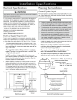
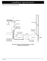
Installation Specifications • The raised vent exhaust may be configured to vent through the bottom or through one of the sides. Allow room for the exhaust duct coming out of the unit. See Planning the Duct Work (page 7) for additional details. • The maximum allowable duct run must be taken into consideration when determining the layout. See Planning the Duct Work for further details. • Access from the front of the cabinet to the underside of the cooktop, the vent system and the electrical and gas supplies for the cooktop and vent must be provided for inspection and service. Any drawers or shelves placed below the cooktop and in front of the vent must be easy to remove for access to the cooktop, vent and utilities. • For installation with gas cooktops, a 90-degree elbow must be connected to the cooktop gas inlet (see diagram at right) to avoid interference with the raised vent's front panel. REMP16 series remote blower 90° elbow Gas line with regulator attached Raised vent with cabinet blower mounted to front Cabinet blower 3 1/4" X 10" to 10" round transition and 45° adjustable elbow Example of Gas Line Routing for Gas Cooktop Installations - Side View Wall board Backsplash Cooktop Backsplash Cooktop Raised vent Duct work between raised vent and remote blower Raised vent configured for bottom exhaust Floor Wiring/conduit that supplies power to remote blower (see Electrical Installation, page 10) Example of Layout with Remote Blower, Roof Exhaust Cabinet blower Wall 3 1/4" X 10" 90° elbow Floor Duct directly through rear wall to wall cap Wall cap 12" Min. (305 mm) Example of Layout with Cabinet Blower, Exhaust Through Wall 5
-
 1
1 -
 2
2 -
 3
3 -
 4
4 -
 5
5 -
 6
6 -
 7
7 -
 8
8 -
 9
9 -
 10
10 -
 11
11 -
 12
12 -
13
-
14
-
15
-
16
-
17
-
18
-
19
-
20
 |
 |
