Danby DPAC120068 Owners Manual - Page 8
location,making
 |
View all Danby DPAC120068 manuals
Add to My Manuals
Save this manual to your list of manuals |
Page 8 highlights
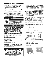
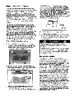
Window / Patio Door Kit Installation (Air Conditioning Mode ONLY) Your window kit has been designed to fit most standard "vertical" / "horizontal" windows and patio doors up to a maximum height of 80". For vertical window and/or patio door applications, lock positions are provided on thefornt of each slider section. Wing nuts are provided (on the slider sect i on) to secure the section together. Fig. 5a. Horizontal Window • Window Slider Kit Minimum: 28" (71.1 cm) Maximum: 48 (123 cm) a + Fig. 3 Rain Hood Assembly 1) Fold both sides of the Rain Hood 90° as so the flanges are facing outward. Fig 1 Fig. 3a Rain hood inserts are installed in "A" and "B" postions with vent opening facing down (C) 2) Slide the Rain Hood flanges onto the edges of the slider kit until it is lined up with the intake vent (shown in Fig 2). Once the mounting holes on the slider, as well as the Rain Hood are aligned, secure the Rain Hood to the slider with the four mounting screws provided. 4 Vertical Wind Rain Hoodis to be installed only over air intake vent N Rain Hood Slider kit Window Slider Kit Minimum: 28" (71.1 cm) Maximum: 48 3/8" (123 cm) Fig. 2 Intake hose adapter IMPORTANT: • For horizontal window kit applications refer to figure 3a for correct Rain Hood insert positioning. • For vertical window kit applications (includingpatio) refer to figure 4a for correct Rain Hood insert positioning. 1) Select a suitable location,making sure you have access to an electrical outlet. 2) Install both flexible hoses to the rear side of the unit. Both hoses are identical and can be installed into either opening. Insert the hose collar with the 2 lock tabs into the 2 slots on the top of each opening and twist to lock into position. 3) Install the adjustable Window/Patio Door Slider Kit as required. Fig's. 3, 4, 5. Rain hood inserts are installed in "A" and "C" positions with vent opening facing down (B) Fig.4a Please Note: In a vertical application, the exhaust hose MUST be positioned above the intake hose in the window slider. See Fig 5. This will avoid having the exhaust heat go through the intake and back into the unit. Patio Door 4) Install the window exhaust adapters into the openings in the slider section, making sure the window slider sections are secure. Important:: Ensure the exhaust adapter labeled "air intake" is installed on the hose that is connected to the air intake opening on the back of the unit. 7 fig. 5a Fig. 5 Air exhaust Air intake Patio Door Kit Minimum: 28" (67.5 cm) Maximum: 80" (203 cm) Plug the unit into a 115 V / 60 Hz grounded electrical outlet.
-
 1
1 -
2
-
 3
3 -
 4
4 -
 5
5 -
 6
6 -
 7
7 -
 8
8 -
 9
9 -
 10
10 -
 11
11 -
 12
12 -
 13
13 -
14
-
15
-
16
-
17
-
18
-
19
-
20
-
21
-
22
 |
 |
