Dell Alienware M11x Service Manual - Page 37
Replacing the System Board
 |
View all Dell Alienware M11x manuals
Add to My Manuals
Save this manual to your list of manuals |
Page 37 highlights
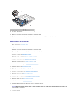
1 system board 2 screws (3) 3 AC adapter cable connector 16. Remove the three screws that secure the system board to the computer base. 17. Carefully ease the connectors on the system board out of the slots in the computer, and lift the system board out of the computer. Replacing the System Board 1. Follow the instructions in Before You Begin. 2. Align the connectors on the system board with the slots on the computer and place it on the computer base. 3. Replace the three screws that secure the system board to the computer base. 4. Connect the AC adapter connector cable to the connector on the system board. 5. Replace the I/O board (see Replacing the I/O Board). 6. Replace the display assembly (see Replacing the Display Assembly). 7. Replace the coin-cell battery (see Replacing the Coin-Cell Battery). 8. Replace the Bluetooth™ card (see Replacing the Bluetooth Card). 9. Replace the palm rest assembly (see Replacing the Palm Rest Assembly). 10. Replace the keyboard (see Replacing the Keyboard). 11. Replace the hinge cover (see Replacing the Hinge Cover). 12. Replace the memory module(s) (see Replacing the Memory Module(s)). 13. Replace the Mini-Card(s) (see Replacing the Mini-Card(s)). 14. Replace the hard-drive assembly (see Replacing the Hard-Drive Assembly). 15. Replace the battery pack (see Replacing the Battery Pack). 16. Replace the base cover (see Replacing the Base Cover). 17. Replace any cards or blank that you removed from the 3-in-1 Media Card reader slot. CAUTION: Before turning on the computer, replace all screws and ensure that no stray screws remain inside the computer. Failure to do so may result in damage to the computer. 18. Turn on the computer.
-
 1
1 -
2
-
3
-
4
-
5
-
6
-
7
-
8
-
9
-
10
-
11
-
12
-
13
-
14
-
15
-
16
-
17
-
18
-
19
-
20
-
21
-
22
-
23
-
24
-
25
-
26
-
27
-
28
-
29
-
30
-
31
-
 32
32 -
 33
33 -
 34
34 -
 35
35 -
 36
36 -
 37
37 -
 38
38 -
 39
39
 |
 |
