Dell Force10 S25-01-GE-24P Setup and Buffer Tuning of the S25P for Storage Env - Page 7
Basic Layer 2 Setup and Buffer Tuning of the S50N for Storage Environments, Command Syntax
 |
View all Dell Force10 S25-01-GE-24P manuals
Add to My Manuals
Save this manual to your list of manuals |
Page 7 highlights
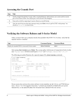
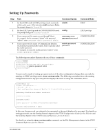
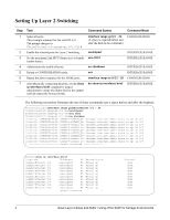
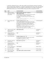
To apply the configuration, above, to other stack members, use the following commands. The interface range used and port-pipes ("port-set 0-1") designated would depend on the S-Series model. The following sequence presumes that the subject stack member is an S25P model. For an example of configuring an S50N model, see Basic Layer 2 Setup and Buffer Tuning of the S50N for Storage Environments. Step 1 2 3 4 5 6 7 8 9 10 Task Command Syntax Command Mode Apply the "eql-hig" buffer profile to another stack member. Select all ports on the switch. Apply the "eql-fp" buffer profile to the ports selected above. Change modes from INTERFACE RANGE to CONFIGURATION. Select all 1GbE ports. Enable flow control on the 1GbE ports. Change modes from INTERFACE RANGE to EXEC privilege. Save the configuration to non-volatile memory. Restart the system. Verify that the buffer profile is applied. buffer fp-uplink stack-unit 0-7 port-set 0 buffer-policy eql-hig For the variable 0-7, enter the stack ID of the stack member to which to apply the "eql-hig" configuration. For example, for an S25P switch with a stack ID of 1, the command is: buffer fp-uplink stack-unit 1 port-set 0 buffer-policy eql-hig CONFIGURATION interface range gi slot/port - port For the variable slot/port, enter the stack ID of the target stack member, along with 1 for the beginning port number in the range and 24 for the highest-numbered 1GbE port. For example, for an S25P switch with a stack ID of 1, the command is: interface range gi 1/1 - 24 If the switch has 10 GbE modules inserted, include the 10 GbE port range in the command, for example: interface range gi 1/1 - 24, te 1/25 - 28 CONFIGURATION buffer-policy eql-fp INTERFACE RANGE exit INTERFACE RANGE interface range gi slot/1 - 24 For slot, enter the stack ID of of the target stack member. For example, for a stack ID of 1, enter: interface range gi 1/1 - 24 flow-control rx on tx on end CONFIGURATION INTERFACE RANGE INTERFACE RANGE write memory EXEC privilege reload show buffer-profile summary fp-uplink EXEC privilege EXEC privilege 101-00337-00 7
-
 1
1 -
 2
2 -
 3
3 -
 4
4 -
 5
5 -
 6
6 -
 7
7 -
 8
8
 |
 |