Dell Force10 S5000 Installation Guide
Dell Force10 S5000 Manual
 |
View all Dell Force10 S5000 manuals
Add to My Manuals
Save this manual to your list of manuals |
Dell Force10 S5000 manual content summary:
- Dell Force10 S5000 | Installation Guide - Page 1
Dell Networking S5000 Installation Guide - Dell Force10 S5000 | Installation Guide - Page 2
of data and tells you how to avoid the problem. WARNING: A WARNING indicates a potential for property damage, personal injury, or death. © 2013 Dell Inc. Trademarks used in this text: Dell™, the Dell logo, Dell Boomi™, Dell Precision™ , OptiPlex™, Latitude™, PowerEdge™, PowerVault™, PowerConnect - Dell Force10 S5000 | Installation Guide - Page 3
Contents 1 About this Guide...5 Related Publications...5 2 Introduction...7 Product Description...7 3 Unpacking the Switch...9 Important Points Before You You Begin...21 Install the S5000 Chassis in a Rack or Cabinet...22 To install the S5000 system, Dell Networking recommends completing the - Dell Force10 S5000 | Installation Guide - Page 4
of Compliance...46 Safety Standards and Compliance Agency Certifications 47 Electromagnetic Compatibility (EMC)...47 Product Recycling and Disposal...48 9 Technical Support...49 The iSupport Website...49 Accessing iSupport Services...49 Requesting a Hardware Replacement...49 Contacting Technical - Dell Force10 S5000 | Installation Guide - Page 5
Configuration Guide for the S5000 Switch • FTOS Command Line Reference Guide for the S5000 Switch • FTOS Release Notes for the S5000 Switch NOTE: For the most recent documentation and software, visit iSupport (registration for access to some sections is required): http://www.dell.com/support/manuals - Dell Force10 S5000 | Installation Guide - Page 6
6 - Dell Force10 S5000 | Installation Guide - Page 7
basic information about installing the S5000 switch. For information about how to configure and monitor switch features, refer to the FTOS Configuration Guide for the S5000 Switch, which is available on the Dell Support website at http://support.dell.com/manuals. This document contains the following - Dell Force10 S5000 | Installation Guide - Page 8
8 - Dell Force10 S5000 | Installation Guide - Page 9
received your ordered items. For example, if you order one S5000 switch, the following items are included. WARNING: If any item is missing or damaged, contact your Dell Networking representative or reseller for instructions. WARNING: Electrostatic discharge (ESD) damage can occur if components are - Dell Force10 S5000 | Installation Guide - Page 10
port ALSO supports 4 × 10GbE mode) Hardware Installation Overview To install the S5000, follow these steps: 1. Attach the mounting brackets. 2. Install the S5000 chassis into a 4-post rack or cabinet. 3. Ground the rack. 4. Install the Ethernet and/or Fibre Channel modules (Fibre Channel module must - Dell Force10 S5000 | Installation Guide - Page 11
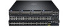
QSFP+ Ports and light emitting diodes (LEDs) Figure 2. S5000 I/O Panel 1. Slot 0 (supports Ethernet and Fibre Channel modules) 2. Slot 1 (supports only Ethernet modules) 3. Slot 2 (supports only Ethernet modules) 4. Slot 3 (supports only Ethernet modules) 5. Four 40GbE QSFP+ ports (each port ALSO - Dell Force10 S5000 | Installation Guide - Page 12
PSU 0) 2. Slot 1 (for Fan Module 0) 3. Slot 2 (for Fan Module 1) 4. Slot 3 (for PSU 1) 5. Grab Handles Power Supplies The S5000 supports two hot-swappable PSUs. NOTE: The PSUs must be installed at the customer site. The S5000 has SKUs that support the following configurations: • AC PSU with fan - Dell Force10 S5000 | Installation Guide - Page 13
10GbE mode. The S5000 supports the following possible modules: • 12-Port Ethernet Module (1G/10G speeds) (slot 0, 1, 2, or 3) • 12-Port Fibre Channel Module (2G/4G/8G Line Reference Guide and FTOS Configuration Guide for the S5000 Switch. As shown in the following figure, the S5000 includes LED - Dell Force10 S5000 | Installation Guide - Page 14
Figure 5. System LEDs (Utility Panel) (AC Power Supplies installed) 1. Locator beacon LED 2. Alarm LED 3. System status LED 4. Master LED 5. Seven-segment display to identify Stack ID 6. PSU status LED 7. Fan status LED NOTE: For AC PSUs, an illuminated translucent handle indicates the power - Dell Force10 S5000 | Installation Guide - Page 15
is booting • System in card problem state • Switch in Stacking Master mode OR Switch in Standalone mode • Switch in Stacking Standby mode • Switch in Stacking Member mode • Normal operation • Power not present • Normal operation • Power not present Figure 7. Module LEDs 1. Port locator beacon LED - Dell Force10 S5000 | Installation Guide - Page 16
No link or interface disabled • Link present and interface enabled (Ethernet module) • Port has activity • No activity • Module beacon/locator • Module is not powered up • Module is powered up • Problem detected with module Description • No activity • Port beacon/locator • Fibre Channel mode enabled - Dell Force10 S5000 | Installation Guide - Page 17
Figure 8. QSFP+ Port LEDs 1. Port link/activity LED Table 4. 40GbE Port/Module LEDs Label Port link/activity LED LED Color/Display • Off • Green solid • Green blinking Description • No link or interface disabled • Link present and interface enabled • Port has activity 17 - Dell Force10 S5000 | Installation Guide - Page 18
18 - Dell Force10 S5000 | Installation Guide - Page 19
Dell Networking equipment is intended for installation in restricted access areas. A restricted access area can only be accessed by service the front, rear, and sides of the S5000 for proper ventilation and access. Cabinet Placement Install the S5000 only in indoor cabinets designed for use in - Dell Force10 S5000 | Installation Guide - Page 20
Storing Components If you do not install your S5000 and components immediately, Dell Networking recommends properly storing the system and all optional components until you are ready to install them. WARNING: ESD damage can occur when components are - Dell Force10 S5000 | Installation Guide - Page 21
• Rack Mounting Safety Considerations • Installing the S5000 Chassis into a 4-post rack or cabinet • Rack Grounding • Important Points to Remember for Installing an Ethernet Module • Installing an Ethernet Module • Replacing an Ethernet Module • Important Points to Remember for Installing a Fan - Dell Force10 S5000 | Installation Guide - Page 22
connector. • Switch is rack-mounted before you install the power supply modules. • Cabling switch, can draw dust and other particles causing contaminant buildup inside the chassis, which can result in system malfunction. Install the S5000 Chassis in a Rack or Cabinet To install the S5000 system, Dell - Dell Force10 S5000 | Installation Guide - Page 23
temperature. Use care not to exceed the 40°C maximum ambient temperature of the switch. • Reduced air flow - Install the equipment in the rack so that the the downward position. WARNING: These instructions are a condensed reference. Read the safety instructions in your Safety, Environmental, and - Dell Force10 S5000 | Installation Guide - Page 24
4-Post Rack or Cabinet NOTE: Dell Networking recommends that one person hold the S5000 chassis in place while a second power service uses in your area. The ground path must be permanent. Important Points to Remember for Installing an Ethernet Module • Installing and swapping of Ethernet modules - Dell Force10 S5000 | Installation Guide - Page 25
when handling the S5000 and its components. NOTE: For the Ethernet module, the part name and port number are inscribed on the handle, as shown in the following figure: NOTE: A blue color release latch indicates that the Ethernet module does not support hot swapping during switch operations. Instead - Dell Force10 S5000 | Installation Guide - Page 26
an Ethernet Module 1. Release latch 2. Ethernet Module Replacing an Ethernet Module NOTE: S5000 does not support the hot swapping of an Ethernet pluggable module during switch operations. Instead, you must power down the switch before removing and replacing an expansion module. 1. Disconnect any - Dell Force10 S5000 | Installation Guide - Page 27
strap when handling the S5000 and its components. NOTE: The part name and port number of a Fibre Channel module are inscribed on the Module Handle 1. Part Name 2. Port Number Installing a Fibre Channel Module 1. Use the grab handle on the Fibre Channel module to slide it into the switch module - Dell Force10 S5000 | Installation Guide - Page 28
information, refer to the System Logs chapters of the FTOS Command Line Reference Guide for the S5000 Switch and FTOS Configuration Guide for the S5000 Switch. WARNING: Although the switch can run on one PSU, Dell Networking highly recommends using two PSUs for full redundancy and proper cooling. If - Dell Force10 S5000 | Installation Guide - Page 29
edge connector is at the bottom. Avoid installing the switch upside down. WARNING: Electrostatic discharge (ESD) damage can occur if components are mishandled. Always wear an ESDpreventive wrist or heel ground strap when handling the S5000 and its components. CAUTION: DO NOT mix airflow directions - Dell Force10 S5000 | Installation Guide - Page 30
the power cable before you service the power supply slots. CAUTION S5000 chassis. • The S5000 supports AC and DC power supplies with two air-flow directions (I/O to Utility and Utility to I/O). The S5000 does not support Guide for the S5000 Switch and FTOS Configuration Guide for the S5000 Switch. 30 - Dell Force10 S5000 | Installation Guide - Page 31
switch upside down. WARNING: Electrostatic discharge (ESD) damage can occur if components are mishandled. Always wear an ESDpreventive wrist or heel ground strap when handling the S5000 or national codes and practices. Damage due to servicing that Dell Networking did not authorize is not covered by - Dell Force10 S5000 | Installation Guide - Page 32
washer 5. #6-32 nut Installing a DC Power Supply 1. Remove the PSU from the electro-static bag. 2. Use the grab handle to slide the PSU into the switch PSU slot (install the PSU-exposed PCB edge connector first). The PSU slot is keyed so that the PSU can be fully inserted in only - Dell Force10 S5000 | Installation Guide - Page 33
Figure 18. Installing a DC Power Supply 1. Slot 0 (for DC PSU 0) 2. Release latch 3. Strip the insulation from the ends of the DC power wires, exposing approximately 13 mm (0.5 inch) of copper wire. WARNING: Reversing polarity when connecting DC power wires can permanently damage the power supply or - Dell Force10 S5000 | Installation Guide - Page 34
and the power source. CAUTION: Always disconnect the power cable before you service the power supply slots. CAUTION: Use the power supply cord as the Cables Add a ferrite bead to the DC power and return cables of the master module. Install the bead with a single loop. 1. Open ferrite bead with the - Dell Force10 S5000 | Installation Guide - Page 35
Figure 20. Installing the Ferrite Bead for DC Power and Return Cables 1. Ferrite Bead 2. DC Power and Return Cables 3. Leave approximately 4 to 5 inches of the DC power and return cables end protruding from the ferrite. 4. Snap the ferrite bead shut. Securing Power Cables 1. Bend the system power - Dell Force10 S5000 | Installation Guide - Page 36
logging command. For more information, refer to the System Logs chapters of the FTOS Command Line Reference Guide for the S5000 Switch and FTOS Configuration Guide for the S5000 Switch. CAUTION: DO NOT mix airflow directions. The airflow directions are color coded. A red label indicates that hot - Dell Force10 S5000 | Installation Guide - Page 37
48 small form-factor pluggable plus (SFP+) optical ports and four QSFP+ optical ports. For a list of supported optics, refer to the S5000 data sheet: http://www.dell.com/us/enterprise/p/force10-s-series/pd. CAUTION: ESD damage can occur if the components are mishandled. Always wear an ESD-preventive - Dell Force10 S5000 | Installation Guide - Page 38
four 10GbE SFP+ ports using one of the supported breakout cables. For a list of supported optics, refer to the S5000 data sheet: http://www.dell.com/us/enterprise/p/force10-s-series/pd. • Configure the system to recognize the port mode change. CONFIGURATION mode stack-unit unit-number port number - Dell Force10 S5000 | Installation Guide - Page 39
the systems while they are powered down or up. Stacking ports are bidirectional. The S5000 supports stacking in either a ring or a daisy-chain topology. To provide redundant connectivity, Dell Networking recommends using the ring topology when stacking S5000 systems. Figure 24. Stacking Topology 39 - Dell Force10 S5000 | Installation Guide - Page 40
data transfer between the systems, Dell Networking recommends inserting an additional cable between the two units, in a second stacking port. You can use any of the SFP+ or QSFP+ ports for stacking, provided it is configured as a stacking port. CAUTION: The S5000 does not require special stacking - Dell Force10 S5000 | Installation Guide - Page 41
module when the system is powered up, the system does not recognize the module. Online insertion of modules can result in a catastrophic failure. Dell higher than the room temperature) is within the limits specified for the S5000. • There is sufficient airflow around the chassis. • The input circuits - Dell Force10 S5000 | Installation Guide - Page 42
come online. So, when setting up a new set of switches in a stack, you should have no trouble forcing the identification of the management unit and unit IDs by Stacking chapter in the FTOS Configuration Guide for the S5000 Switch and the Stacking Commands chapter in the FTOS Command Line - Dell Force10 S5000 | Installation Guide - Page 43
incorrectly replaced. NOTE: Replace the battery only with same or equivalent type. Dispose of the batteries according to the manufacturer's instructions. Table 5. Chassis Physical Design Parameter Specifications Height 1.71 inches (43.5 mm) Width 17.4 inches (441 mm) Depth 28 inches (711 - Dell Force10 S5000 | Installation Guide - Page 44
44 - Dell Force10 S5000 | Installation Guide - Page 45
energy. If it is not installed and used in accordance to the instructions, it may cause harmful interference to radio communications. Operation of this connectors must be used in order to meet FCC emission limits. Dell Networking is not responsible for any radio or television interference caused by - Dell Force10 S5000 | Installation Guide - Page 46
A Equipment WARNING: Use the AC power cords with Dell Networking equipment only. Do not use Dell Networking AC power cords with any unauthorized hardware. This in a domestic environment, radio disturbance may arise. When such trouble occurs, the user may be required to take corrective actions. - Dell Force10 S5000 | Installation Guide - Page 47
• EN 60950-1, Second Edition • EN 60825-1, First Edition • EN 60825-1 Safety of Laser Products - Part 1: Equipment Classification Requirements and User's Guide • EN 60825-2 Safety of Laser Products - Part 2: Safety of Optical Fibre Communication Systems • FDA Regulation 21CFR 1040.10 and 1040.11 - Dell Force10 S5000 | Installation Guide - Page 48
by WEEE. For information on Dell Networking product recycling offerings, see the WEEE Recycling instructions on iSupport at: http://downloads.dell.com/Manuals/all-products/esuprt_electronics/esuprt_docking_stations/dell-superspeed-usb3dock-stn_Reference%20Guide_en-us.pdf?c=us&l=en&cs=&s=gen 48 - Dell Force10 S5000 | Installation Guide - Page 49
URL for iSupport is http://www.force10networks.com/ CSPortal20/Main/Login.aspx . You must have a userid and password to access iSupport services. 1. On the Dell Networking Support page, click the Account Request link. 2. Fill out the User Account Request form and click Send. You will receive your - Dell Force10 S5000 | Installation Guide - Page 50
support command.) • Console captures showing the error messages • Console captures showing the troubleshooting steps taken • Saved messages to a syslog server, if you use one Log in to iSupport and select the Service : [email protected] Web: http://support.dell.com/ Telephone: •
-
 1
1 -
 2
2 -
 3
3 -
 4
4 -
 5
5 -
 6
6 -
 7
7 -
8
-
9
-
10
-
11
-
12
-
13
-
14
-
15
-
16
-
17
-
18
-
19
-
20
-
21
-
22
-
23
-
24
-
25
-
26
-
27
-
28
-
29
-
30
-
31
-
32
-
33
-
34
-
35
-
36
-
37
-
38
-
39
-
40
-
41
-
42
-
43
-
44
-
45
-
46
-
47
-
48
-
49
-
50
 |
 |

Dell Networking S5000
Installation Guide