Dell Force10 S5000 Installation Guide - Page 25
Installing an Ethernet Module, Port Number
 |
View all Dell Force10 S5000 manuals
Add to My Manuals
Save this manual to your list of manuals |
Page 25 highlights
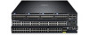
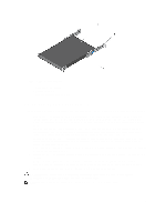
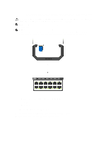
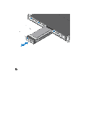
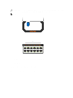
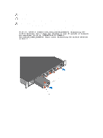
- A smaller handle that is half the size and does not cover the release button. The part number is written on the front of the handle. Port numbering is written on the lower part of the front of the module. WARNING: Electrostatic discharge (ESD) damage can occur if components are mishandled. Always wear an ESDpreventive wrist or heel ground strap when handling the S5000 and its components. NOTE: For the Ethernet module, the part name and port number are inscribed on the handle, as shown in the following figure: NOTE: A blue color release latch indicates that the Ethernet module does not support hot swapping during switch operations. Instead, you must power down the switch before removing and replacing an Ethernet module. A red color release latch indicates that the Ethernet module supports hot swapping during switch operations. Figure 11. Part name and Port number on the Ethernet Module Handle 1. Part Name 2. Port Number Installing an Ethernet Module 1. Use the grab handle on the Ethernet module to slide it into the switch module slot. 2. Connect any network interface cables to the attached module. 25
-
 1
1 -
2
-
3
-
4
-
5
-
6
-
7
-
8
-
9
-
10
-
11
-
12
-
13
-
14
-
15
-
16
-
17
-
18
-
19
-
 20
20 -
 21
21 -
 22
22 -
 23
23 -
 24
24 -
 25
25 -
 26
26 -
 27
27 -
 28
28 -
 29
29 -
 30
30 -
31
-
32
-
33
-
34
-
35
-
36
-
37
-
38
-
39
-
40
-
41
-
42
-
43
-
44
-
45
-
46
-
47
-
48
-
49
-
50
 |
 |
