Dell Force10 Z9000 Dell Force10 Z9000 System Quick Start Guide
Dell Force10 Z9000 Manual
 |
View all Dell Force10 Z9000 manuals
Add to My Manuals
Save this manual to your list of manuals |
Dell Force10 Z9000 manual content summary:
- Dell Force10 Z9000 | Dell Force10 Z9000 System Quick Start Guide - Page 1
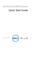
Dell Force10 Z9000 System Quick Start Guide Regulatory Model: Z9000 - Dell Force10 Z9000 | Dell Force10 Z9000 System Quick Start Guide - Page 2
- Dell Force10 Z9000 | Dell Force10 Z9000 System Quick Start Guide - Page 3
Dell Force10 Z9000 System Quick Start Guide Regulatory Model: Z9000 - Dell Force10 Z9000 | Dell Force10 Z9000 System Quick Start Guide - Page 4
to hardware or loss of data if instructions are not followed. WARNING: notice. © 2011 Dell Inc. All rights Dell Inc. is strictly forbidden. Trademarks used in this text: Dell™, the DELL logo, Dell of Dell Inc. Intel®, Pentium®, Xeon®, Core™ and Dell Inc. disclaims any proprietary interest in trademarks - Dell Force10 Z9000 | Dell Force10 Z9000 System Quick Start Guide - Page 5
, refer to the following documents: Documentation Z9000 Hardware installation and power-up Installing the Z9000 System instructions Software configuration FTOS Configuration Guide for the Z9000 Command line interface FTOS Command Reference for the Z9000 Latest updates FTOS Release Notes for - Dell Force10 Z9000 | Dell Force10 Z9000 System Quick Start Guide - Page 6
4 About this Guide - Dell Force10 Z9000 | Dell Force10 Z9000 System Quick Start Guide - Page 7
1 Installing the Hardware This guide assumes all site preparation has been performed before installing the chassis. Installing the Z9000 Chassis in a Rack or Cabinet To install the Z9000 system, Dell Force10 recommends that you complete the installation procedures in the order presented below. - Dell Force10 Z9000 | Dell Force10 Z9000 System Quick Start Guide - Page 8
of the chassis. I/O side Rack/Cabinet Mounting Ears Rack/Cabinet Post Install chassis into rack or cabinet Step Task 1 Dell Force10 recommends that one person hold the Z9000 chassis in place while a second person attaches the brackets to the posts. 2 Attach the bracket "ears" to the rack - Dell Force10 Z9000 | Dell Force10 Z9000 System Quick Start Guide - Page 9
Cable length must facilitate the proper operation of fault interrupt circuits. Dell Force10 recommends using the shortest cable route allowable. 3 Attach the one Optics The Z9000 has 32 QSFP+ optical ports. For supported optics, refer to http://www.force10networks.com/products/specifications.asp. - Dell Force10 Z9000 | Dell Force10 Z9000 System Quick Start Guide - Page 10
the 40G optics be inserted with the tabs facing up. Splitting QSFP Ports to SFP+ Ports The Z9000 supports splitting a single 40G QSFP port into four 10G SFP+ ports using one of the supported breakout cables. You must enter the stack-unit portmode command for the system to recognize the port type - Dell Force10 Z9000 | Dell Force10 Z9000 System Quick Start Guide - Page 11
Power Up the System Dell Force10 recommends re-inspecting your system AC power connector, making sure that the power cord is secure. As soon as the cable is connected between the Z9000 and the power source, the chassis is powered-up; there is no on/off switch. DC Power To connect the plug to the DC - Dell Force10 Z9000 | Dell Force10 Z9000 System Quick Start Guide - Page 12
the DC connectors. As soon as the cable is connected between the Z9000 and the power source, the chassis is powered-up; there is no on/off switch. Fans The Z9000 comes The switch never intentionally turns off the fans. Use the show logging command to see the log messages. Z9000 Specifications - Dell Force10 Z9000 | Dell Force10 Z9000 System Quick Start Guide - Page 13
Maximum System Power Input Specifications 36 to 72 VDC 2.8A @ 36 VDC 1.85 A @ 72 VDC 360 W Power Supplies The Z9000 is designed to support two hot-swappable power supplies. NOTE: If using a single PSU, you must install a blank plate in the other PSU slot. Dell Force10 recommends using PSU0, if - Dell Force10 Z9000 | Dell Force10 Z9000 System Quick Start Guide - Page 14
modules should slide into the slots smoothly. Do not force a module into a slot. This may damage the power supply or the Z9000 chassis. PSU0 Fan Modules PSU1 DC cable connectors Securing Screw Grab Handle Step Task 1 Take the power supply unit out of the shipping box. 2 Remove the small - Dell Force10 Z9000 | Dell Force10 Z9000 System Quick Start Guide - Page 15
use a console connection when connecting to the system for the first time. Serial Console The RJ-45/RS-232 console port is labeled on the Z9000 chassis. It is in the upper right-hand side, as you face the I/O side of the chassis. Primary Management (Ethernet) Port RJ-45/RS-232 - Dell Force10 Z9000 | Dell Force10 Z9000 System Quick Start Guide - Page 16
Step Task 3 Terminal settings on the console port cannot be changed in the software and are set as follows: 9600 baud rate No parity 8 data bits 1 stop bit No flow control Accessing the RJ-45 console port with a DB-9 adapter You can connect to the console using an RJ-45 - Dell Force10 Z9000 | Dell Force10 Z9000 System Quick Start Guide - Page 17
, which is Force10). You must configure the system using the Command Line Interface (CLI). Configure Layer 2 (Data Link) Mode Use the switchport command in INTERFACE mode to enable Layer 2 data transmissions through an individual interface. The user can not configure switching or Layer 2 protocols - Dell Force10 Z9000 | Dell Force10 Z9000 System Quick Start Guide - Page 18
Access the System Remotely You can configure the system to be accessed remotely by Telnet. The Z-Series has a dedicated management port and a management routing table that is separate from the IP routing table. Step Task 1 Configure an IP address for the management port. 2 Configure a management - Dell Force10 Z9000 | Dell Force10 Z9000 System Quick Start Guide - Page 19
using a DES encryption method. • enable secret is stored in the running/startup configuration in using a stronger, MD5 encryption method. Dell Force10 recommends using the enable secret password. Task Command Syntax Create a password to enable [password | secret] [level level] access EXEC - Dell Force10 Z9000 | Dell Force10 Z9000 System Quick Start Guide - Page 20
Create a Port-based VLAN The Default VLAN as VLAN 1 is part of the system startup configuration and does not require configuration. To configure a port-based VLAN, you must create the VLAN and then add physical interfaces or port channel (LAG) interfaces to the VLAN. Task Configure a port-based - Dell Force10 Z9000 | Dell Force10 Z9000 System Quick Start Guide - Page 21
Command Syntax Configure an IP address ip address ip-address mask and mask on the interface. [secondary] Command Mode INTERFACE Connecting the Z9000 to the Network Once you have completed the hardware installation and software configuration, you can connect to your company network by following - Dell Force10 Z9000 | Dell Force10 Z9000 System Quick Start Guide - Page 22
20 Installing the Software - Dell Force10 Z9000 | Dell Force10 Z9000 System Quick Start Guide - Page 23
- Dell Force10 Z9000 | Dell Force10 Z9000 System Quick Start Guide - Page 24
Printed in the U.S.A. www.dell.com | support.dell.com
-
 1
1 -
 2
2 -
 3
3 -
 4
4 -
 5
5 -
 6
6 -
 7
7 -
8
-
9
-
10
-
11
-
12
-
13
-
14
-
15
-
16
-
17
-
18
-
19
-
20
-
21
-
22
-
23
-
24
 |
 |
Dell Force10 Z9000 System
Quick Start Guide
Regulatory Model: Z9000