Dell Force10 Z9000 Installing the Z9000 System
Dell Force10 Z9000 Manual
 |
View all Dell Force10 Z9000 manuals
Add to My Manuals
Save this manual to your list of manuals |
Dell Force10 Z9000 manual content summary:
- Dell Force10 Z9000 | Installing the Z9000 System - Page 1
Installing the Z9000 System Publication Date: October 2012 - Dell Force10 Z9000 | Installing the Z9000 System - Page 2
damage to hardware or loss of data and tells you how to avoid the problem. WARNING: A WARNING indicates a potential for property damage, personal injury, or death. Information in this publication is subject to change without notice. © 2012 Dell Force10. All rights reserved. Reproduction of these - Dell Force10 Z9000 | Installing the Z9000 System - Page 3
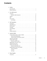
Contents 1 Preface About this Guide 7 Related Publications 7 2 The Z9000 System Introduction 9 Orderable Z9000 Components 10 Features 11 Ports 12 System Status 12 LED Displays Power Up the System 24 Power Up Sequence 25 AC Power 25 DC Power 25 5 Power Supplies Components 27 Contents | 3 - Dell Force10 Z9000 | Installing the Z9000 System - Page 4
dell.com | support.dell.com Install a Power Supply 27 Install a New AC Power Supply 28 Install a New DC Power Supply 28 Replace a Power Supply 29 Replace an AC Power Supply 29 Replace a DC Specifications Chassis Physical Design 41 Environmental Parameters 41 AC Power Requirements 41 DC - Dell Force10 Z9000 | Installing the Z9000 System - Page 5
9 Technical Support The iSupport Website 51 Accessing iSupport Services 51 Contacting the Technical Assistance Center 52 Requesting a Hardware Replacement 53 Contents | 5 - Dell Force10 Z9000 | Installing the Z9000 System - Page 6
www.dell.com | support.dell.com 6 | Contents - Dell Force10 Z9000 | Installing the Z9000 System - Page 7
to the FTOS Command Line Reference Guide for the Z9000 System. NOTE: The Z9000 system requires, at a minimum, Dell Force10 Operating System (FTOS) version guide before you install and power up the Z9000 system. This equipment contains two power cords. Disconnect both power cords before servicing - Dell Force10 Z9000 | Installing the Z9000 System - Page 8
www.dell.com | support.dell.com 8 | Preface - Dell Force10 Z9000 | Installing the Z9000 System - Page 9
Introduction The Dell Force10 Z9000 platform is a next-generation switch/router product designed to meet the requirements for distributed data center cores. It is a two-rack unit (RU) chassis that supports 32 ports of 40GE QSFP+ or 128 ports of 10GE SFP+ (with breakout cables). The Z9000 includes an - Dell Force10 Z9000 | Installing the Z9000 System - Page 10
from the PSU side Z9000-PWR-DC-R to the I/O side Z9000 Series - Solid State Drive (SSD) Z9000-SSD Dell Part Number K9N70 GJKPG G9TXN HRXFM WWJVT FRD2C NY1X9 0XRVV 4JPXV F3WK0 2HYHT Table 2-2. Supported Optics and Cables Optic Size Optic Type Reach (Meters) Force10 Catalog Number 40G QSFP - Dell Force10 Z9000 | Installing the Z9000 System - Page 11
ensure that you have the following: • Z9000 chassis • Optics (Optics must be ordered separately, unit • Spare fan module • Spare optics • Breakout cable Features The Z9000 offers the following: • Z9000 CPU and switch processor • Hot-swappable redundant power supplies • 19-inch rack-mountable • - Dell Force10 Z9000 | Installing the Z9000 System - Page 12
www.dell.com | support.dell.com Ports • External serial RS-232 port (RJ45 type) • Remote management port • 32-port 40G QSFP+ ports • USB-A port • USB-B port • SSD drive System Status You can view the Z9000 status information in several ways, including Light Emitting Diodes (LEDs) and boot menu - Dell Force10 Z9000 | Installing the Z9000 System - Page 13
operation Power supply missing or failed No alarm Minor alarm Critical alarm No activity System beacon/locator As shown in the following figure, the Z9000 includes status indicator LEDs for each port. These ports are described in Table 2-4. When the QSFP+ ports are operating in 40G mode, the left - Dell Force10 Z9000 | Installing the Z9000 System - Page 14
www.dell.com | support.dell.com Table 2-4. Port LED Displays Feature Description QSFP+ Port LED Management (Ethernet) Port LEDs Link LED: • Green-Link up on (left side of the port): • Blinking Green-Activity, transmitting, or receiving packet at this port • Off-No traffic 14 | The Z9000 System - Dell Force10 Z9000 | Installing the Z9000 System - Page 15
to Specifications. NOTE: Install the Z9000 chassis into a rack or cabinet before installing any optional components. Site Selection Dell Force10 equipment is intended for installation in restricted access areas. A restricted access area is one in which access can only be gained by service personnel - Dell Force10 Z9000 | Installing the Z9000 System - Page 16
same ground point used by the power service in your area. The ground path must be permanent. Grounding Use the Z9000 in a Common Bond Network (CBN). You must connect the grounding cables as described in Install the Z9000. Fans and Airflow The Z9000 system fans support two air flow options. Be sure - Dell Force10 Z9000 | Installing the Z9000 System - Page 17
CAUTION: Always disconnect the power cable before the power supply slots are serviced. CAUTION: The power supply cord is used as the main disconnect device not install your system and components immediately, Dell Force10 recommends properly storing the Z9000 and all optional components until you are - Dell Force10 Z9000 | Installing the Z9000 System - Page 18
18 | Site Preparations www.dell.com | support.dell.com - Dell Force10 Z9000 | Installing the Z9000 System - Page 19
4 Install the Z9000 To install the Z9000 system, Dell Force10 recommends completing the installation procedures in the order presented below. Always handle the system and its components with care. Avoid dropping the Z9000 or its Field Replaceable Units (FRUs). This chapter describes the installation - Dell Force10 Z9000 | Installing the Z9000 System - Page 20
www.dell.com | support.dell.com To attach the brackets to the system, follow these steps: the already attached mounting brackets, follow these steps: Step Task NOTE: Dell Force10 recommends using one person to hold the Z9000 in place while another person attaches the brackets to the posts. 20 - Dell Force10 Z9000 | Installing the Z9000 System - Page 21
Ground Cable Use a single M4x0.7 screw to attach the ground cable to the system. The cable itself is not included with the Z9000. To properly ground the system, Dell Force10 recommends using a 6AWG one-hole lug, #10 hole size, 63" spacing (not included in shipping). The one-hole lug must be a UL - Dell Force10 Z9000 | Installing the Z9000 System - Page 22
www.dell.com | support.dell.com Step Task (continued) 3 As shown, attach the one-hole grounding point. Install the QSFP+ Optics The Z9000 has 32 QSFP+ optical ports. For supported optics, refer to http://www.force10networks.com/ products/specifications.asp. WARNING: ESD damage can occur if - Dell Force10 Z9000 | Installing the Z9000 System - Page 23
the Z9000 system and is located in a slot on the lower-right area on the I/O side as shown in the following figure. The SSD is field replaceable but not hot-swappable and supports drives that use 12 Volts and/or 5.0 Volts. Be sure to use only drives supported by Dell Force10. Install the Z9000 | 23 - Dell Force10 Z9000 | Installing the Z9000 System - Page 24
www.dell.com | support.dell.com the System Supply power to the Z9000 after the system is mounted in a rack or cabinet. Dell Force10 recommends re-inspecting your system in place. NOTE: A US AC power cable is included in the shipping container for powering up an AC power supply. You must order all - Dell Force10 Z9000 | Installing the Z9000 System - Page 25
steadily lit green. AC Power To add AC power, connect the plug to each AC power connector. Make sure the power cord is secure. As soon as the cable is connected between the Z9000 system and the power source, the system is powered-up; there is no on/off switch. DC Power To add DC power, follow - Dell Force10 Z9000 | Installing the Z9000 System - Page 26
26 | Install the Z9000 www.dell.com | support.dell.com - Dell Force10 Z9000 | Installing the Z9000 System - Page 27
). The Z9000 supports AC and DC power supplies with two air-flow directions (normal and reversed). Two PSUs are required for full redundancy, but the system will operate with a single PSU. NOTE: If you use a single PSU, you must install a blank plate in the other PSU slot. Dell Force10 recommends - Dell Force10 Z9000 | Installing the Z9000 System - Page 28
www.dell.com | support.dell.com CAUTION: Be sure that the DC power source is turned off before attaching the cables to the DC connectors on the Z9000. Power Supply 0 (PSU0) is on the top of the Z9000; power supply 1(PSU1) is on the bottom of the Z9000 system. Install a New AC Power Supply Figure - Dell Force10 Z9000 | Installing the Z9000 System - Page 29
DC cable connectors. 8 Turn the DC power source ON. Replace a Power Supply NOTE: If a PSU fails, it must be completely replaced. There are no field servicable slot. Dell Force10 recommends using power supply 1 (PSU1) as the blank plate slot. Replace an AC Power Supply To replace an AC PSU, - Dell Force10 Z9000 | Installing the Z9000 System - Page 30
www.dell.com | support.dell.com Replace a DC Power Supply To replace a DC power supply, follow these steps: NOTE: The PSU slides into the slot smoothly. Do not force the PSU into a slot as this may damage the PSU or the chassis. Step Task 1 Turn the DC power source OFF. 2 Remove the small - Dell Force10 Z9000 | Installing the Z9000 System - Page 31
the fan modules are hot-swappable. The Z9000 supports two airflow direction options. Do not mix Z9000 Fan module (Force10 Catalog# Z9000-FAN | Dell Part # WWJVT) • Z9000 Fan module - Reverse flow (Force10 Catalog# Z9000-FAN-R | Dell Part # FRD2C) Install a Fan Module The fan modules in the Z9000 - Dell Force10 Z9000 | Installing the Z9000 System - Page 32
www.dell.com | support.dell.com To install a new fan module, follow these steps: Step Task 1 Twist the latching screws so that the fan screen detaches from the system as - Dell Force10 Z9000 | Installing the Z9000 System - Page 33
Replace a Fan Module To replace a fan module, follow these steps: Step 1 Task Twist the latching screws so that the fan screen detaches from the system. PSU0 Fan Module 0 Fan Module 1 Fan Module 2 Fan Module 3 Grab Handle PSU1 Screw 2 Remove the fan screen and set it aside. 3 Loosen - Dell Force10 Z9000 | Installing the Z9000 System - Page 34
34 | Fans www.dell.com | support.dell.com - Dell Force10 Z9000 | Installing the Z9000 System - Page 35
Task 1 Install an RJ-45 copper cable into the console port. Use a rollover cable to connect the Z9000 console port to a terminal server. 2 Connect the other end of the cable to the Data Terminal Equipment (DTE) serial port on the PC or terminal server. 3 Keep the default terminal settings on - Dell Force10 Z9000 | Installing the Z9000 System - Page 36
are the same for the USB-B port and the console port: • 9600 baud rate • No parity • 8 data bits • 1 stop bit • No flow control When you connect the USB-B port, it becomes the primary connection and for the USB device you use. For assistance, contact Dell Force10 Technical Support. 36 | Access Ports - Dell Force10 Z9000 | Installing the Z9000 System - Page 37
For assistance, contact Dell Force10 Technical Support. 6 Open your terminal software emulation program to access the Z9000. 7 Set the No parity, 8 data bits, 1 stop bit, No flow control The Command Line Interface (CLI) prompt appears (FTOS>_) when you are connected to the Z9000. Access the - Dell Force10 Z9000 | Installing the Z9000 System - Page 38
www.dell.com | support.dell.com Figure 7-3. SSD Drive SSD Handle Components The following SSD option is available: • Z9000 Solid State Drive (Force10 Catalog# Z9000-SSD | Dell Part Number: 2HYHT) Install an SSD To install an SSD, follow these steps: Step Task 1 Shut down the system. You - Dell Force10 Z9000 | Installing the Z9000 System - Page 39
6 drw7 d--- --More-- 8192 8192 Mar 30 1919 10:31:04 CORE_DUMP_DIR Mar 30 1919 10:31:04 ADMIN_DIR Copy Files to and from the SSD To copy files to or from the SSD, use the copy command. For example: Copy from an FTP site to the SSD: FTOS#copy ftp://myusername:[email protected]//FTOS/FTOS-ZB - Dell Force10 Z9000 | Installing the Z9000 System - Page 40
40 | Access Ports www.dell.com | support.dell.com - Dell Force10 Z9000 | Installing the Z9000 System - Page 41
20° to 70°C) No performance degradation to 10,000 feet (3,048 meters) 10 to 85% non-condensing AC Power Requirements Parameter Nominal input voltage Maximum AC power supply input current Maximum system power input Specifications 100 to 240 VAC, 50/60 Hz 8.00 A @ 100/120VAC 4.00 A @ 200/240 VAC 789 - Dell Force10 Z9000 | Installing the Z9000 System - Page 42
dell.com | support.dell.com DC Power Requirements Parameter Nominal input voltage Maximum DC power supply input current Maximum system power input Specifications -40 to -60 VDC 16.5 A @ -48 VDC 789 W IEEE Standards The Z9000 accordance to the instructions, it may limits. Dell Force10 is not - Dell Force10 Z9000 | Installing the Z9000 System - Page 43
a non-recommended modification of this product, including the fitting of non-Dell Force10 option cards. This product has been tested and found to comply with environment, radio disturbance may arise. When such trouble occurs, the user may be required to take corrective actions. Specifications | 43 - Dell Force10 Z9000 | Installing the Z9000 System - Page 44
.dell.com | support.dell.com WARNING: Use the AC Power cords with Dell Force10 equipment only. Do not use Dell Force10 AC EN 60825-1 Safety of Laser Products-Part 1: Equipment Classification Requirements and User's Guide • EN 60825-2 Safety of Laser Products-Part 2: Safety of Optical Fibre - Dell Force10 Z9000 | Installing the Z9000 System - Page 45
services in several countries to assist equipment owners in recycling their IT products. Waste Electrical and Electronic Equipment (WEEE) Directive for Recovery, Recycle and Reuse of IT and Telecommunications Products Dell Force10 switches upon end of life per this Directive. Specifications | 45 - Dell Force10 Z9000 | Installing the Z9000 System - Page 46
Dell Force10 product recycling offerings, see the WEEE Recycling instructions on iSupport at: https://www.force10networks.com/CSPortal20/Support/WEEEandRecycling.pdf. For more information, contact the Dell Force10 off. 3 Gently push the SD card to release it from the slot. 46 | Specifications - Dell Force10 Z9000 | Installing the Z9000 System - Page 47
requires replacement, contact Dell Force10 Technical Support. WARNING: Electrostatic discharge (ESD) damage can occur if components are mishandled. Always wear an ESD-preventive wrist or heel ground strap when handling the Z9000 Specifications | 47 - Dell Force10 Z9000 | Installing the Z9000 System - Page 48
www.dell.com | support.dell.com Step Task (continued) 4 Lever the battery up against the coin cell clip (the hold-down lead on health due to the potential presence of hazardous substances. For proper collection and treatment, contact your local Dell Force10 representative. 48 | Specifications - Dell Force10 Z9000 | Installing the Z9000 System - Page 49
/hazardouswaste/perchlorate The foregoing notice is provided in accordance with California Code of Regulations Title 22, Division 4.5 Chapter 33. Best Management Practices for Perchlorate Materials. Specifications | 49 - Dell Force10 Z9000 | Installing the Z9000 System - Page 50
50 | Specifications www.dell.com | support.dell.com - Dell Force10 Z9000 | Installing the Z9000 System - Page 51
patches, and open and manage your Technical Assistance Center (TAC) cases. Dell Force10 iSupport provides integrated, secure access to these services. Accessing iSupport Services The URL for iSupport is http://www.force10networks.com/support/. You must have a userid and password to access iSupport - Dell Force10 Z9000 | Installing the Z9000 System - Page 52
Center How to Contact Dell Force10 TAC Information to Submit When Opening a Support Case Managing Your Case Downloading Software Updates Technical Documentation Contact Information Log in to iSupport at http://www.force10networks.com/support/ and select the Service Request tab. • Your name - Dell Force10 Z9000 | Installing the Z9000 System - Page 53
support case. Open a support case by: • Using the Create Service Request form on the iSupport page (see Contacting the Technical Assistance Center). • Contacting Dell Force10 -support [non-paged] command.) - Console captures showing the error messages - Console captures showing the troubleshooting - Dell Force10 Z9000 | Installing the Z9000 System - Page 54
54 | Technical Support www.dell.com | support.dell.com - Dell Force10 Z9000 | Installing the Z9000 System - Page 55
- Dell Force10 Z9000 | Installing the Z9000 System - Page 56
Printed in the U.S.A. www.dell.com | support.dell.com
-
 1
1 -
 2
2 -
 3
3 -
 4
4 -
 5
5 -
 6
6 -
 7
7 -
8
-
9
-
10
-
11
-
12
-
13
-
14
-
15
-
16
-
17
-
18
-
19
-
20
-
21
-
22
-
23
-
24
-
25
-
26
-
27
-
28
-
29
-
30
-
31
-
32
-
33
-
34
-
35
-
36
-
37
-
38
-
39
-
40
-
41
-
42
-
43
-
44
-
45
-
46
-
47
-
48
-
49
-
50
-
51
-
52
-
53
-
54
-
55
-
56
 |
 |

Installing the Z9000 System
Publication Date: October 2012