Dell PowerConnect W-IAP Remote Hardware Installation Guide
Dell PowerConnect W-IAP Remote Manual
 |
View all Dell PowerConnect W-IAP Remote manuals
Add to My Manuals
Save this manual to your list of manuals |
Dell PowerConnect W-IAP Remote manual content summary:
- Dell PowerConnect W-IAP Remote | Hardware Installation Guide - Page 1
53-1002267-01 18 March 2011 PowerConnect B-FCX Switch Hardware Installation Guide - Dell PowerConnect W-IAP Remote | Hardware Installation Guide - Page 2
these materials in any manner whatsoever without the written permission of Dell Inc. is strictly forbidden. Trademarks used in this text: Dell, the DELL logo,, Dell OpenManage , and PowerConnect are trademarks of Dell Inc.; Microsoft, Windows, and Windows Server are either trademarks or registered - Dell PowerConnect W-IAP Remote | Hardware Installation Guide - Page 3
Dell ix Chapter 1 Product Overview Hardware features 1 Control features 3 Power supplies 13 Chapter 2 Installing the PowerConnect or replacing fan trays on PowerConnect B-FCX624s and PowerConnect B-FCX648s devices 28 PowerConnect B-FCX Switch Hardware Installation Guide iii 53-1002267-01 - Dell PowerConnect W-IAP Remote | Hardware Installation Guide - Page 4
a route 45 Troubleshooting network connections 45 Using Virtual Cable Testing to diagnose a cable 46 Digital optical monitoring 47 Managing the PowerConnect B-FCX Hardware module 55 Cleaning the fiber optic connectors 55 iv PowerConnect B-FCX Switch Hardware Installation Guide 53-1002267-01 - Dell PowerConnect W-IAP Remote | Hardware Installation Guide - Page 5
Power cords 63 AC power supply specifications 63 Troubleshooting Diagnosing switch indicators 65 Power and cooling problems 65 Installation 65 In-band access 66 Regulatory Danger Notices Cautions 71 Danger notices 73 PowerConnect B-FCX Switch Hardware Installation Guide v 53-1002267-01 - Dell PowerConnect W-IAP Remote | Hardware Installation Guide - Page 6
vi PowerConnect B-FCX Switch Hardware Installation Guide 53-1002267-01 - Dell PowerConnect W-IAP Remote | Hardware Installation Guide - Page 7
a Dell Layer 3 Switch, you should be familiar with the following protocols if applicable to your network - IP, RIP, OSPF, BGP, ISIS, IGMP, PIM, DVMRP, and VRRP. Supported hardware and software The following hardware platform is supported in this release: • PowerConnect B-FCX624s • PowerConnect - Dell PowerConnect W-IAP Remote | Hardware Installation Guide - Page 8
danger notices The following note, cautions, and danger statements are used in this manual. They are listed here in order of increasing severity of potential hazards. NOTE following Dell documents supplement the information in this guide: • PowerConnect B-FCX Series Configuration Guide - Provides - Dell PowerConnect W-IAP Remote | Hardware Installation Guide - Page 9
service issues: 1. Visit http://support.dell.com. 2. Click your country or region at the bottom of the page. For a full listing of countries and regions, click All. 3. In the Support menu, click All Support. Choose the method of contacting Dell that is convenient for you. PowerConnect B-FCX - Dell PowerConnect W-IAP Remote | Hardware Installation Guide - Page 10
x PowerConnect B-FCX Switch Hardware Installation Guide 53-1002267-01 - Dell PowerConnect W-IAP Remote | Hardware Installation Guide - Page 11
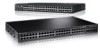
Product Overview Chapter 1 Hardware features The following hardware platforms are supported by this release of this guide: • The PowerConnect B-FCX624s stackable switch has twenty 10/100/1000 Mbps RJ45 ports plus four Combo ports, which include four 10/100/1000 Mbps RJ45 ports and - Dell PowerConnect W-IAP Remote | Hardware Installation Guide - Page 12
power supply receptacles accommodate up to two power supply units that also support a back-to-front cooling airflow. NOTE All PowerConnect B-FCX models support Layer 2 and Enterprise Layer 3 protocols (RIP, OSPF, PIM). PowerConnect B-FCX models can be ordered from the factory as -ADV (Advanded Layer - Dell PowerConnect W-IAP Remote | Hardware Installation Guide - Page 13
MUST BE THE SAME AIRFLOW AIRFLOW Control features Each device front panel includes the following control features: • Serial management interface (the DB9 port labeled Console) PowerConnect B-FCX Switch Hardware Installation Guide 3 53-1002267-01 - Dell PowerConnect W-IAP Remote | Hardware Installation Guide - Page 14
one of these ports does not support auto-negotiation, the communication mode of the port can be configured manually. Combination ports PowerConnect B-FCX devices contain four combination ports RJ45 port or SFP slot, as required. 4 PowerConnect B-FCX Switch Hardware Installation Guide 53-1002267-01 - Dell PowerConnect W-IAP Remote | Hardware Installation Guide - Page 15
support. Slot designations Table 2 lists the slot designations for PowerConnect B-FCX models. TABLE 2 Device Stack unit slots for PowerConnect B-FCX stackable devices Slot 1 Slot 2 Slot 3 PowerConnect ) PowerConnect B- PowerConnect 20 PowerConnect module PowerConnect panel PowerConnect - Dell PowerConnect W-IAP Remote | Hardware Installation Guide - Page 16
SFP interfaces Table 3 describes the network interfaces supported on PowerConnect B-FCX devices. TABLE 3 Interface SFP network up to 40Km. Optional two-port 10 Gbps XFP uplink module The PowerConnect B-FCX624s and PowerConnect B-FCX648s devices include a slot on the front panel for a two-port - Dell PowerConnect W-IAP Remote | Hardware Installation Guide - Page 17
LC cables. These devices cannot be combined in a stack with non-PowerConnect B-FCX devices. For detailed information about how to configure PowerConnect B-FCX devices in an IronStack topology, see the PowerConnect B-FCX Series Configuration Guide. NOTE The 1 Gbps SFP and 10 Gbps SFP+ modules are - Dell PowerConnect W-IAP Remote | Hardware Installation Guide - Page 18
display panel for key system and port indicators that simplifies installation and network troubleshooting. The LEDs, which are located on the front panel for easy viewing, are shown below and described in the following tables. 8 PowerConnect B-FCX Switch Hardware Installation Guide 53-1002267-01 - Dell PowerConnect W-IAP Remote | Hardware Installation Guide - Page 19
port is operating at 1000 Mbps. The SFP port is operating at 100 Mbps. A link is not established with a remote port. 1 Slot 3 A/S 1 System status LEDs PowerConnect B-FCX Switch Hardware Installation Guide 9 53-1002267-01 - Dell PowerConnect W-IAP Remote | Hardware Installation Guide - Page 20
OK AC OK Power status LEDs Condition Green Red Green Off Status DC output ok DC output fail AC input ok AC input fail 10 PowerConnect B-FCX Switch Hardware Installation Guide 53-1002267-01 - Dell PowerConnect W-IAP Remote | Hardware Installation Guide - Page 21
PowerConnect B-FCX624 and PowerConnect B-FCX648 PowerConnect B-FCX switches include a display panel for key system and port indicators that simplifies installation and network troubleshooting not established with a remote port. PowerConnect B-FCX Switch Hardware Installation Guide 11 53-1002267-01 - Dell PowerConnect W-IAP Remote | Hardware Installation Guide - Page 22
a valid link at 10/100/1000 Mbps. Flashing indicates the port is transmitting and receiving user packets. A link is not established with a remote port. 12 PowerConnect B-FCX Switch Hardware Installation Guide 53-1002267-01 - Dell PowerConnect W-IAP Remote | Hardware Installation Guide - Page 23
device has two power receptacles on the rear panel. Each device ships with one power supply installed. PowerConnect B-FCX624s, PowerConnect B-FCX648s, PowerConnect B-FCX624, and PowerConnect B-FCX648 devices use a 210W PSU. PowerConnect B-FCX Switch Hardware Installation Guide 13 53-1002267-01 - Dell PowerConnect W-IAP Remote | Hardware Installation Guide - Page 24
easy monitoring and troubleshooting. A secondary swappable. For instructions on installing PowerConnect B-FCX624s and PowerConnect B-FCX648s AC power supply receptacle 1 1 AC power receptacle FIGURE 17 PowerConnect B-FCX624 and PowerConnect must be green for the PowerConnect B-FCX device to function - Dell PowerConnect W-IAP Remote | Hardware Installation Guide - Page 25
this manual are intended for qualified service personnel. CAUTION Before beginning the installation, see the precautions in "Power precautions" on page 17. Unpacking the device PowerConnect B- or using the CLI through Telnet. PowerConnect B-FCX Switch Hardware Installation Guide 15 53-1002267-01 - Dell PowerConnect W-IAP Remote | Hardware Installation Guide - Page 26
can use Brocade Guide Network Advisor to manage the device. 11 Secure access to the device. PowerConnect B-FCX Series Configuration Guide Installation precautions Follow all precautions when installing a Dell device. 16 PowerConnect B-FCX Switch Hardware Installation Guide 53-1002267-01 - Dell PowerConnect W-IAP Remote | Hardware Installation Guide - Page 27
provides redundancy in case one of the circuits fails. CAUTION To avoid high voltage shock, do not open the device while the power is on. PowerConnect B-FCX Switch Hardware Installation Guide 17 53-1002267-01 - Dell PowerConnect W-IAP Remote | Hardware Installation Guide - Page 28
site. Refer to "Hardware Specifications" on page 57 for a summary of supported cabling types and their specifications. Installation location Before installing the device, plan interference, such as radios and transmitters. 18 PowerConnect B-FCX Switch Hardware Installation Guide 53-1002267-01 - Dell PowerConnect W-IAP Remote | Hardware Installation Guide - Page 29
equipment, a filter or surge suppressor is recommended. Installing the device You can install Dell devices on a desktop or in an equipment rack, use appropriate retainer nuts and screws on top of the one below, in any order. PowerConnect B-FCX Switch Hardware Installation Guide 19 53-1002267-01 - Dell PowerConnect W-IAP Remote | Hardware Installation Guide - Page 30
for installation. NOTE For additional support for the stack of switches, refer to the Dell 1U shelf, Dell part number-G118R, which is device as illustrated in Figure 19 and Figure 20. NOTE PowerConnect B-FCX624 and PowerConnect B-FCX648 brackets are mounted using three screws, as shown in - Dell PowerConnect W-IAP Remote | Hardware Installation Guide - Page 31
are connected between switches in a stack. The connection is based on 10G/16G Gigabit Ethernet, using CX4 cables. PowerConnect B-FCX devices support linear and ring stack topologies, and can also operate as standalone devices. PowerConnect B-FCX Switch Hardware Installation Guide 21 53-1002267-01 - Dell PowerConnect W-IAP Remote | Hardware Installation Guide - Page 32
5 illustrates a ring-topology stacking configuration. You can form a stack containing up to eight PowerConnect B-FCX units. To connect switches in a stack, perform the following steps: 1. Plug ) and ring (bottom) topology stack 22 PowerConnect B-FCX Switch Hardware Installation Guide 53-1002267-01 - Dell PowerConnect W-IAP Remote | Hardware Installation Guide - Page 33
Guide. PowerConnect B-FCX624 and PowerConnect B-FCX648 devices Figure 23 and Figure 24 show how stacking cables are connected between PowerConnect B-FCX624 and PowerConnect B-FCX648 devices in a stack. The connection is based on 10 Gbps SFP+ using LC-LC MM Fiber cables. These devices support - Dell PowerConnect W-IAP Remote | Hardware Installation Guide - Page 34
. 2. Attach the AC power cable to the AC connector on the rear panel. 3. Insert the power cable plug into a 115V, 120V, or 240V outlet. 24 PowerConnect B-FCX Switch Hardware Installation Guide 53-1002267-01 - Dell PowerConnect W-IAP Remote | Hardware Installation Guide - Page 35
Stop bits: 1 • Flow control: None The EIA or TIA 232 serial communication port serves as a connection point for management by a PC or SNMP workstation. Dell devices come with a standard male DB-9 connector, shown in Figure 26. PowerConnect B-FCX Switch Hardware Installation Guide 25 53-1002267-01 - Dell PowerConnect W-IAP Remote | Hardware Installation Guide - Page 36
requiring either a DB-9 or DB-25 connector, male or female. Serial cable options between a Dell device and a PC or terminal are shown in Table 16. Wiring map for serial cable TABLE 16 an "I" as shown in Table 1 on page 3. 26 PowerConnect B-FCX Switch Hardware Installation Guide 53-1002267-01 - Dell PowerConnect W-IAP Remote | Hardware Installation Guide - Page 37
potential static electricity. Dell recommends using an ESD wrist strap during installation. 3. Remove the PSU from the anti-static shielded bag. 4. Holding the PSU level, guide it into the slot, the system will overheat. PowerConnect B-FCX Switch Hardware Installation Guide 27 53-1002267-01 - Dell PowerConnect W-IAP Remote | Hardware Installation Guide - Page 38
and fan trays are clearly labeled with either a green arrow with an "E", or an orange arrow with an "I" as shown in Table 1 on page 3. 28 PowerConnect B-FCX Switch Hardware Installation Guide 53-1002267-01 - Dell PowerConnect W-IAP Remote | Hardware Installation Guide - Page 39
Remove the fan tray from the anti-static shielded bag. 4. Holding the fan tray level, guide it into the carrier rails on each side and gently push it all the way into the the environmental temperature surrounding the switch. PowerConnect B-FCX Switch Hardware Installation Guide 29 53-1002267-01 - Dell PowerConnect W-IAP Remote | Hardware Installation Guide - Page 40
PowerConnect B-FCX624s or PowerConnect B-FCX648s devices Installing an optional module on PowerConnect B-FCX624s or PowerConnect B-FCX648s devices FIGURE 30 Installing an optional module PowerConnect B-FCX624s and PowerConnect B-FCX648s switches support the module level, guide it into the carrier - Dell PowerConnect W-IAP Remote | Hardware Installation Guide - Page 41
PowerConnect B-FCX624 and PowerConnect B-FCX648 devices 2 Installing an optional module in PowerConnect B-FCX624 and PowerConnect B-FCX648 devices PowerConnect B-FCX624 and PowerConnect B-FCX648 switches support shielded bag. 4. Hold the module level, guide it into the carrier rails and gently push - Dell PowerConnect W-IAP Remote | Hardware Installation Guide - Page 42
module in PowerConnect B-FCX624 and PowerConnect B-FCX648 devices CAUTION If you do not install a module in a slot, you must keep the slot panel in place. If you run the device with an uncovered slot, the system will overheat. 32 PowerConnect B-FCX Switch Hardware Installation Guide 53-1002267 - Dell PowerConnect W-IAP Remote | Hardware Installation Guide - Page 43
The procedures in this manual are for qualified service personnel. Assigning permanent passwords By default, the CLI is not protected by passwords. To secure CLI access, Dell strongly recommends assigning passwords. See the PowerConnect B-FCX Series Configuration Guide. NOTE You cannot assign - Dell PowerConnect W-IAP Remote | Hardware Installation Guide - Page 44
to recover from a lost password. 1. Start a CLI session over the serial interface to the Dell device. 2. Reboot the device. 3. While the system is booting, before the initial system prompt reappears, assign a new password. 34 PowerConnect B-FCX Switch Hardware Installation Guide 53-1002267-01 - Dell PowerConnect W-IAP Remote | Hardware Installation Guide - Page 45
before you can manage the system using the other management interfaces. Dell devices support both classical IP network masks (Class A, B, and C subnet change the display to the prefix format. See the PowerConnect B-FCX Series Configuration Guide. Devices running Layer 2 software Use the following - Dell PowerConnect W-IAP Remote | Hardware Installation Guide - Page 46
press Enter. This command erases the factory test configuration if still present: PowerConnect# erase startup-config CAUTION Use the erase startup-config command only for new : [no] ip address / [secondary] 36 PowerConnect B-FCX Switch Hardware Installation Guide 53-1002267-01 - Dell PowerConnect W-IAP Remote | Hardware Installation Guide - Page 47
virtual routing interface itself. Dell devices support both classical IP network masks problems that can occur due to unstable links between a Layer 3 Switch and other devices. You can configure up to four loopback interfaces on a Layer 3 switch. PowerConnect B-FCX Switch Hardware Installation Guide - Dell PowerConnect W-IAP Remote | Hardware Installation Guide - Page 48
PowerConnect(config)# int loopback 1 PowerConnect(config-lbif-1)# ip address 10.0.0.1/24 Syntax: interface loopback The parameter specifies the virtual interface number. You can specify from 1 to the maximum number of virtual interfaces supported IP address. PowerConnect(config-if-1/1/1)# - Dell PowerConnect W-IAP Remote | Hardware Installation Guide - Page 49
PowerConnect(config-if-1/1/1)# no ip address * Syntax: no ip address | * Connecting network devices Dell devices support cable. For more information about this feature, see the PowerConnect B-FCX Series Configuration Guide. FIGURE 32 UTP crossover cable 10/100BASE-TX Crossover - Dell PowerConnect W-IAP Remote | Hardware Installation Guide - Page 50
All 10/100 and Gbps Ethernet Copper ports on the devices support automatic Media Dependent Interface (MDI) and Media Dependent Interface Crossover about this feature and how configure it, refer to PowerConnect B-FCX Series Configuration Guide. Connecting a network device to a fiber port For direct - Dell PowerConnect W-IAP Remote | Hardware Installation Guide - Page 51
No 40km No TABLE 18 Supported SFP transceivers for PowerConnect B-FCX624 and PowerConnect B-FCX648 10 Gigabit Optic Distance Supported for stacking 10GSFPP-SR 10GSFPP- are keyed to prevent incorrect insertion. PowerConnect B-FCX Switch Hardware Installation Guide 41 53-1002267-01 - Dell PowerConnect W-IAP Remote | Hardware Installation Guide - Page 52
link and active LEDs to determine if the network connections are functioning properly. For more information about the LED indicators, refer to Table 19. 42 PowerConnect B-FCX Switch Hardware Installation Guide 53-1002267-01 - Dell PowerConnect W-IAP Remote | Hardware Installation Guide - Page 53
Testing connectivity 3 Cleaning the fiber optic connectors To avoid problems with the connection between the fiber optic transceiver (SFP, SFP+, or mini-GBIC) each LED, and what to do if an LED indicates an abnormal state. PowerConnect B-FCX Switch Hardware Installation Guide 43 53-1002267-01 - Dell PowerConnect W-IAP Remote | Hardware Installation Guide - Page 54
the transmit port on the Dell device is connected to the receive port on the other network shared with the SFP port. • If the other actions don't resolve the problem, try using a different port or a different cable. A link is not PowerConnect B-FCX Switch Hardware Installation Guide 53-1002267-01 - Dell PowerConnect W-IAP Remote | Hardware Installation Guide - Page 55
Link LED. If a problem persists after taking these actions, contact Dell Technical Support. Tracing a route To determine the path through which a Dell device can reach another device, enter a command similar to the following at any level of the CLI on the device. PowerConnect> traceroute 192.33 - Dell PowerConnect W-IAP Remote | Hardware Installation Guide - Page 56
Troubleshooting problem, try using a different port or a different cable. Using Virtual Cable Testing to diagnose a cable These devices support . In this case, Dell recommends that you run PowerConnect# show cable-diag tdr 1/1/1 46 PowerConnect B-FCX Switch Hardware Installation Guide 53-1002267-01 - Dell PowerConnect W-IAP Remote | Hardware Installation Guide - Page 57
Troubleshooting network connections 3 The output from this command appears below. PowerConnect# show cable-diag tdr 1/1/1 Port Speed Local pair Pair monitoring, refer to PowerConnect B-FCX Series Configuration Guide. PowerConnect B-FCX Switch Hardware Installation Guide 47 53-1002267-01 - Dell PowerConnect W-IAP Remote | Hardware Installation Guide - Page 58
3 Troubleshooting network connections 48 PowerConnect B-FCX Switch Hardware Installation Guide 53-1002267-01 - Dell PowerConnect W-IAP Remote | Hardware Installation Guide - Page 59
Managing the PowerConnect B-FCX Hardware 4 CAUTION The procedures in this manual are for qualified service personnel. -C 2 -> 3 @ 67 deg-C 2 - Dell PowerConnect W-IAP Remote | Hardware Installation Guide - Page 60
log, enter the show log command at any CLI level. PowerConnect# show log Syslog logging: enabled (0 messages dropped, 0 flushes a command similar to the following at the Privileged EXEC level of the CLI: PowerConnect# temperature warning 1 85 Syntax: temperature warning The < - Dell PowerConnect W-IAP Remote | Hardware Installation Guide - Page 61
53.0 deg-C Boot Prom MAC : 0012.f2d4.69c0 Management MAC: 0012.f2d4.69c0 PowerConnect(config-unit-1)# Syntax: fan-threshold speed-3 mp The capable of registering negative temperature settings. PowerConnect B-FCX Switch Hardware Installation Guide 51 53-1002267-01 - Dell PowerConnect W-IAP Remote | Hardware Installation Guide - Page 62
value> can be 0 - 125. Enter the show chassis command to confirm the change: PowerConnect# show chassis The stack unit 1 chassis info: Power supply 1 (NA-AC-Regular)present Temperature Readings: Current temperature : 47.5 deg-C 52 PowerConnect B-FCX Switch Hardware Installation Guide 53-1002267-01 - Dell PowerConnect W-IAP Remote | Hardware Installation Guide - Page 63
PowerConnect similar to the following at the global CONFIG level: PowerConnect(config)# chassis poll-time 2 200 Syntax: chassis EXEC level of the CLI: PowerConnect# clear mac-address 000d.cb80.00d0 PowerConnect B-FCX CPU usage You can display the amount of the PowerConnect CLI: PowerConnect# show cpu - Dell PowerConnect W-IAP Remote | Hardware Installation Guide - Page 64
Hardware maintenance schedule Hardware maintenance schedule PowerConnect B-FCX switch hardware components require minimal maintenance. Dell recommends cleaning the fiber-optic connectors on latch is enclosed in a blue sleeve. 54 PowerConnect B-FCX Switch Hardware Installation Guide 53-1002267-01 - Dell PowerConnect W-IAP Remote | Hardware Installation Guide - Page 65
a fiber optic module refer to "Cabling a fiber optic transceiver" on page 42. Cleaning the fiber optic connectors For instructions on cleaning a fiber optic module refer to "Cleaning the fiber optic connectors" on page 43. PowerConnect B-FCX Switch Hardware Installation Guide 55 53-1002267-01 - Dell PowerConnect W-IAP Remote | Hardware Installation Guide - Page 66
4 Replacing a copper or fiber optic module 56 PowerConnect B-FCX Switch Hardware Installation Guide 53-1002267-01 - Dell PowerConnect W-IAP Remote | Hardware Installation Guide - Page 67
15.19 in 43.5 cm 17.13 in 4 kg (8.8 lbs) 5.35 kg (11.79 lbs) PowerConnect B-FCX648 4.4 cm 1.7 in 44 cm 17.32 in 43.5 cm 17.13 in 5.71 kg (12 F) 5 to 95%, @ 40 C (104.9F), non-condensing 0 - 3000 meters (10,000 feet) PowerConnect B-FCX Switch Hardware Installation Guide 57 53-1002267-01 - Dell PowerConnect W-IAP Remote | Hardware Installation Guide - Page 68
1 on page 3. For an illustration of the fan tray labels, see "Power supply and fan tray labels for PowerConnect B-FCX624-E, PowerConnect B-FCX624-I, PowerConnect B-FCX648-E, and PowerConnect B-FCX648-I devices" on page 3. 58 PowerConnect B-FCX Switch Hardware Installation Guide 53-1002267-01 - Dell PowerConnect W-IAP Remote | Hardware Installation Guide - Page 69
Inflow 2 Air outlet FIGURE 40 PowerConnect B-FCX624-E and PowerConnect B-FCX648-E device airflow 2 MCgomntsoleReset PS 1 2 Diag 1 1 Air Inflow 2 Air outlet 1 3 5 7 9 11 2 4 6 8 10 12 13 15 17 19 21 23 14 16 18 20 22 24 PowerConnect B-FCX Switch Hardware Installation Guide 59 53-1002267-01 - Dell PowerConnect W-IAP Remote | Hardware Installation Guide - Page 70
5 Hardware specifications FIGURE 41 PowerConnect B-FCX624-I and PowerConnect B-FCX648-I device airflow 1 MCgomntsoleReset PS 1 2 Diag 2 1 3 5 7 9 11 2 4 6 8 10 compliances refer to "Regulatory compliance" on page 69. 60 PowerConnect B-FCX Switch Hardware Installation Guide 53-1002267-01 - Dell PowerConnect W-IAP Remote | Hardware Installation Guide - Page 71
1 2 2 3 3 4 Reserved 4 5 5 6 Reserved 6 7 7 8 8 9 Reserved 9 DB-9 to DB-25 Female Switch Terminal or PC 1 Reserved 8 2 3 3 2 4 Reserved 20 5 7 6 Reserved 6 7 4 8 5 9 Reserved 22 PowerConnect B-FCX Switch Hardware Installation Guide 61 53-1002267-01 - Dell PowerConnect W-IAP Remote | Hardware Installation Guide - Page 72
Ethernet ports. For information about supported transceivers, see Table 17 and Table recommendations, consult your local Dell reseller or system engineer. - 550 2 - 550 2 - 10000 .5 - 275 .5 - 550 .5 - 595 .5 - 740 .5 - 860 62 PowerConnect B-FCX Switch Hardware Installation Guide 53-1002267-01 - Dell PowerConnect W-IAP Remote | Hardware Installation Guide - Page 73
3 power usage, these devices can support up to 48 ports. TABLE 25 AC power supply specifications Input voltage range Input current (PSU x 1) PowerConnect B-FCX624s PowerConnect B-FCX648s PowerConnect B-FCX624-E PowerConnect B-FCX624-I PowerConnect B-FCX648-E PowerConnect B-FCX648-I 100 - 240 VAC - Dell PowerConnect W-IAP Remote | Hardware Installation Guide - Page 74
5 Hardware specifications 64 PowerConnect B-FCX Switch Hardware Installation Guide 53-1002267-01 - Dell PowerConnect W-IAP Remote | Hardware Installation Guide - Page 75
. If you still cannot isolate the problem, then the internal power supply may be defective. In this case, contact Technical Support for assistance. Installation Verify that all the other components are functioning properly. PowerConnect B-FCX Switch Hardware Installation Guide 65 53-1002267-01 - Dell PowerConnect W-IAP Remote | Hardware Installation Guide - Page 76
the switch with a valid IP address, subnet mask, and default gateway. If you have trouble establishing a link to the management agent, check to see if you have a valid network between your remote location and the switch. 66 PowerConnect B-FCX Switch Hardware Installation Guide 53-1002267-01 - Dell PowerConnect W-IAP Remote | Hardware Installation Guide - Page 77
installed and used in accordance with the instruction manual, may cause harmful interference to radio made to this device which are not expressly approved by Dell could void the user's authority to operate the equipment. PowerConnect B-FCX Switch Hardware Installation Guide 67 53-1002267-01 - Dell PowerConnect W-IAP Remote | Hardware Installation Guide - Page 78
equipment is used in a domestic environment, radio disturbance may arise. When such trouble occurs, the user may be required to take corrective actions. Japan power note of this. C 2-ɋɉȾ-0560 29 2009 ɝ. ɞɨ 29 2012 ɝ. 68 PowerConnect B-FCX Switch Hardware Installation Guide 53-1002267-01 - Dell PowerConnect W-IAP Remote | Hardware Installation Guide - Page 79
Compatibility (EMC), Immunity standards, and safety agency approvals for the PowerConnect B-FCX family of switches. .TABLE 27 Regulatory Compliance and Safety /UL 60950-1-07 • EN 60950-1:2006 +A11:2009 • IEC 60950-1:2005 PowerConnect B-FCX Switch Hardware Installation Guide 69 53-1002267-01 - Dell PowerConnect W-IAP Remote | Hardware Installation Guide - Page 80
A Regulatory compliance 70 PowerConnect B-FCX Switch Hardware Installation Guide 53-1002267-01 - Dell PowerConnect W-IAP Remote | Hardware Installation Guide - Page 81
posible peligro que pueda dañar el equipo. Las siguientes son precauciones utilizadas en este manual. CAUTION VORSICHT MISE EN GARDE PRECAUCIÓN Do not install the device in an environment de que uno de los circuitos falle. PowerConnect B-FCX Switch Hardware Installation Guide 71 53-1002267-01 - Dell PowerConnect W-IAP Remote | Hardware Installation Guide - Page 82
configuración en un sistema ya configurado, introduzca el comando write memory (escribir memoria) para guardar la configuración en ejecución en el archivo startup-config. 72 PowerConnect B-FCX Switch Hardware Installation Guide 53-1002267-01 - Dell PowerConnect W-IAP Remote | Hardware Installation Guide - Page 83
hazard that can cause injury or death. The following are the warnings used in this manual. "Gefahr" weist auf eine mögliche Gefährdung hin, die zu Verletzungen oder Tod trouverez les avertissements utilisés dans ce manuel. PowerConnect B-FCX Switch Hardware Installation Guide 73 53-1002267-01 - Dell PowerConnect W-IAP Remote | Hardware Installation Guide - Page 84
par le personnel de service qualifié uniquement. Los procedimientos de este manual se han hecho para wackeln oder umfallen kann. Vérifiez que le bâti ou le support abritant le dispositif est bien fixé afin qu'il ne devienne . 74 PowerConnect B-FCX Switch Hardware Installation Guide 53-1002267-01 - Dell PowerConnect W-IAP Remote | Hardware Installation Guide - Page 85
une résistance de série 1 méga ohm. Por razones de seguridad, la correa de muñeca ESD deberá contener un resistor en serie de 1 mega ohmio. PowerConnect B-FCX Switch Hardware Installation Guide 75 53-1002267-01 - Dell PowerConnect W-IAP Remote | Hardware Installation Guide - Page 86
B Danger notices 76 PowerConnect B-FCX Switch Hardware Installation Guide 53-1002267-01
-
 1
1 -
 2
2 -
 3
3 -
 4
4 -
 5
5 -
 6
6 -
 7
7 -
8
-
9
-
10
-
11
-
12
-
13
-
14
-
15
-
16
-
17
-
18
-
19
-
20
-
21
-
22
-
23
-
24
-
25
-
26
-
27
-
28
-
29
-
30
-
31
-
32
-
33
-
34
-
35
-
36
-
37
-
38
-
39
-
40
-
41
-
42
-
43
-
44
-
45
-
46
-
47
-
48
-
49
-
50
-
51
-
52
-
53
-
54
-
55
-
56
-
57
-
58
-
59
-
60
-
61
-
62
-
63
-
64
-
65
-
66
-
67
-
68
-
69
-
70
-
71
-
72
-
73
-
74
-
75
-
76
-
77
-
78
-
79
-
80
-
81
-
82
-
83
-
84
-
85
-
86
 |
 |

53-1002267-01
18 March 2011
PowerConnect B-FCX
Switch
Hardware Installation Guide