Dell PowerConnect W-IAP Remote Hardware Installation Guide - Page 18
Gbps Ethernet CX4 stacking ports, Port, system
 |
View all Dell PowerConnect W-IAP Remote manuals
Add to My Manuals
Save this manual to your list of manuals |
Page 18 highlights
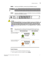
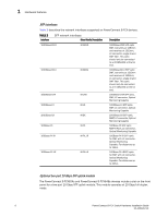
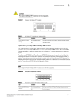
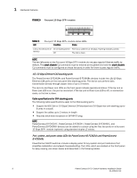
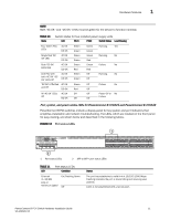
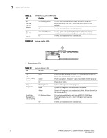
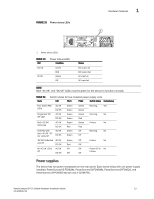
1 Hardware features FIGURE 9 Four-port 10 Gbps SFP+ module FCX-4XG X1 X2 X3 X4 TABLE 6 LED Four-port 10 Gbps SFP+ module status LEDs Condition Status Link or Act LED (Link or On or flashing Green Port has a valid link at 10 Gbps. Flashing indicates activity. Activity) Off The link is down. NOTE The two left ports on the Four-port 10Gbps SFP+ module do not pass regular Ethernet traffic by default. The stack disable CLI command must be entered at the global level and the stack disable CLI command must be configured on these two ports in order for them to pass regular traffic. 16/10 Gbps Ethernet CX4 stacking ports The PowerConnect B-FCX624s and PowerConnect B-FCX648s devices include two 16/10 Gbps Ethernet CX4 ports on the rear panel (the stacking ports). The device can perform data transmission directly through copper links of up to 3 meters. The Up Link and Down Link LEDs on the front panel indicate operational status. If the Up Link or Down Link LED is on, the port is connected. If the Up Link or Down Link LED is off, no connection exists, or the link is down. Cable specifications for CX4 stacking ports The following cable specifications apply to the CX4 stacking ports: • Support for 802.3ak or 10 Gbps Ethernet CX4 standard and 16 Gbps inter-unit stacking (up to 8 units in a stack) • Support for cables up to 3 meters in length • Requires latch-style receptacle or SFF-8470 plug NOTE PowerConnect B-FCX624-E, PowerConnect B-FCX624-I, PowerConnect B-FCX648-E, and PowerConnect B-FCX648-I devices can be added to a stack using the first two ports on a four-port 10 Gbps SFP+ module (optional) using standard duplex LC cables. Port, system, and power status LEDs for PowerConnect B-FCX624s and PowerConnect B-FCX648s PowerConnect B-FCX switches include a display panel for key system and port indicators that simplifies installation and network troubleshooting. The LEDs, which are located on the front panel for easy viewing, are shown below and described in the following tables. 8 PowerConnect B-FCX Switch Hardware Installation Guide 53-1002267-01
-
 1
1 -
2
-
3
-
4
-
5
-
6
-
7
-
8
-
9
-
10
-
11
-
12
-
 13
13 -
 14
14 -
 15
15 -
 16
16 -
 17
17 -
 18
18 -
 19
19 -
 20
20 -
 21
21 -
 22
22 -
 23
23 -
24
-
25
-
26
-
27
-
28
-
29
-
30
-
31
-
32
-
33
-
34
-
35
-
36
-
37
-
38
-
39
-
40
-
41
-
42
-
43
-
44
-
45
-
46
-
47
-
48
-
49
-
50
-
51
-
52
-
53
-
54
-
55
-
56
-
57
-
58
-
59
-
60
-
61
-
62
-
63
-
64
-
65
-
66
-
67
-
68
-
69
-
70
-
71
-
72
-
73
-
74
-
75
-
76
-
77
-
78
-
79
-
80
-
81
-
82
-
83
-
84
-
85
-
86
 |
 |