Dell PowerEdge 2321DS User Manual - Page 9
Four Post Front of Rack Cabling, Connecting the Cables to the KVM, Routing the Power Cables and Data
 |
View all Dell PowerEdge 2321DS manuals
Add to My Manuals
Save this manual to your list of manuals |
Page 9 highlights
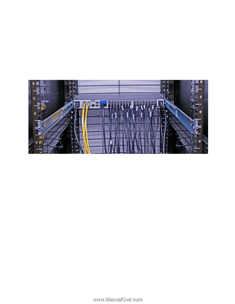
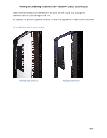
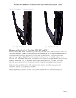
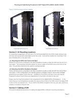
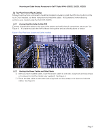
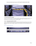
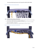
Mounting and Cable Routing Procedures for Dell™ Digital KVM's (1082DS, 2162DS, 4322DS) 3.1 Four Post Front of Rack Cabling Follow the instructions contained in the Rack Installation Guide to install the KVM into the front of the rack. Once installed, use these instructions to install the cables. All illustrations in the following sections were created using the Dell KVM 4322DS. 3.1.1 Connecting the Cables to the KVM Connect all applicable cables to the rear of the system and verify that all connections are secure. See Figure 4. It is easier to cable the KVM without having other devices directly above or below. Figure 4: Four Post Rack: System and Cables Installed 3.1.2 Routing the Power Cables and Data Cables 1.) After you have installed cables, route the power cables to one side, using hook and loop straps or tie downs to hold the cables (user supplied). See Figure 5. 2.) Route the data cables to the other side using hook and loop straps or tie downs to hold the cables. See Figure 5. Page 7
-
 1
1 -
2
-
3
-
 4
4 -
 5
5 -
 6
6 -
 7
7 -
 8
8 -
 9
9 -
 10
10 -
 11
11 -
 12
12 -
 13
13
 |
 |