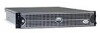
Dell PowerEdge 2650 Cabling Instructions for the –48 VDC - Page 5
Insert the three red °48 VDC return wires into connector housing positions 1
 |
View all Dell PowerEdge 2650 manuals
Add to My Manuals
Save this manual to your list of manuals |
Page 5 highlights
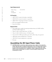
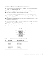
To construct the DC input power cable, perform the following steps: 1 Strip the insulation from the ends of the six DC power wires, exposing approximately 4.5 mm (0.175 inches) of copper wire. 2 Using a hand-crimping tool, crimp a connector contact to each DC power wire. 3 Slide a piece of heat-shrink tubing over the DC power cable. The heat-shrink tubing should be approximately 3.175 cm (1.25 inches) in length. 4 Insert the three black -48 VDC wires into connector housing positions 2, 3, and 6 (see Figure 1-1 and Table 1-1). 5 Insert the three red -48 VDC return wires into connector housing positions 1, 4, and 5 (see Figure 1-1 and Table 1-1). 6 Slide the heat-shrink tubing over the DC power cable so that it overlaps the connector housing by at least 6.35 mm (0.25 inches). 7 Using a heat gun, shrink the tubing around the cable and connector housing. Figure 1-1. Connector Housing front view 6 3 5 2 4 1 Table 1-1. Connect or Housing Pin Ass ignments Pin Description 1 -48 VDC return 2 -48 VDC 3 -48 VDC 4 -48 VDC return 5 -48 VDC return 6 -48 VDC Wire Color and Size Red 16 AWG Black 16 AWG Black 16 AWG Red 16 AWG Red 16 AWG Black 16 AWG Cabling Instructions for the -48 VDC 1-3
-
 1
1 -
 2
2 -
 3
3 -
 4
4 -
 5
5 -
 6
6 -
 7
7 -
 8
8
 |
 |
