Dell PowerEdge T310 Hardware Owner's Manual - Page 129
Installing a Processor, rocessor
 |
View all Dell PowerEdge T310 manuals
Add to My Manuals
Save this manual to your list of manuals |
Page 129 highlights
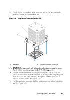
12 Carefully, lift the processor out of the socket and leave the release lever up so that the socket is ready for the new processor. 13 After removing the processor, place it in an antistatic container for reuse, return, or temporary storage. NOTE: Do not touch the bottom of the processor. Touch only the side edges of the processor. If you are permanently removing the processor, you must install a processor blank and a heat-sink blank in the CPU socket to ensure proper system cooling. 14 Adding the blank is similar to installing a processor. See "Installing a Processor" on page 129. Installing a Processor 1 Unpack the new processor. 2 Align the processor with the socket keys on the ZIF socket. See Figure 3-23. 3 Install the processor in the socket. CAUTION: Positioning the processor incorrectly can permanently damage the system board or the processor. Be careful not to bend the pins in the socket. 4 With the release lever on the processor socket in the open position, align the processor with the socket keys and set the processor lightly in the socket. CAUTION: Do not use force to seat the processor. When the processor is positioned correctly, it engages easily into the socket. 5 Close the processor shield. 6 Rotate the socket release lever down until it snaps into place. 7 Using a clean lint-free cloth, remove the thermal grease from the heat sink. 8 Open the grease packet included with your processor kit and apply thermal grease evenly to the top of the new processor. 9 Place the heat sink on the processor. See Figure 3-23. 10 Using a #2 Phillips screwdriver, tighten the heat-sink retention screws. See Figure 3-22. 11 Replace the cooling shroud. See "Installing the Cooling Shroud" on page 89. 12 Replace the expansion card stabilizer. See "Installing the Expansion Card Stabilizer" on page 87. Installing System Components 129
-
 1
1 -
2
-
3
-
4
-
5
-
6
-
7
-
8
-
9
-
10
-
11
-
12
-
13
-
14
-
15
-
16
-
17
-
18
-
19
-
20
-
21
-
22
-
23
-
24
-
25
-
26
-
27
-
28
-
29
-
30
-
31
-
32
-
33
-
34
-
35
-
36
-
37
-
38
-
39
-
40
-
41
-
42
-
43
-
44
-
45
-
46
-
47
-
48
-
49
-
50
-
51
-
52
-
53
-
54
-
55
-
56
-
57
-
58
-
59
-
60
-
61
-
62
-
63
-
64
-
65
-
66
-
67
-
68
-
69
-
70
-
71
-
72
-
73
-
74
-
75
-
76
-
77
-
78
-
79
-
80
-
81
-
82
-
83
-
84
-
85
-
86
-
87
-
88
-
89
-
90
-
91
-
92
-
93
-
94
-
95
-
96
-
97
-
98
-
99
-
100
-
101
-
102
-
103
-
104
-
105
-
106
-
107
-
108
-
109
-
110
-
111
-
112
-
113
-
114
-
115
-
116
-
117
-
118
-
119
-
120
-
121
-
122
-
123
-
 124
124 -
 125
125 -
 126
126 -
 127
127 -
 128
128 -
 129
129 -
 130
130 -
 131
131 -
 132
132 -
 133
133 -
 134
134 -
135
-
136
-
137
-
138
-
139
-
140
-
141
-
142
-
143
-
144
-
145
-
146
-
147
-
148
-
149
-
150
-
151
-
152
-
153
-
154
-
155
-
156
-
157
-
158
-
159
-
160
-
161
-
162
-
163
-
164
-
165
-
166
-
167
-
168
-
169
-
170
-
171
-
172
-
173
-
174
-
175
-
176
-
177
-
178
-
179
-
180
-
181
-
182
-
183
-
184
-
185
-
186
-
187
-
188
-
189
-
190
-
191
-
192
-
193
-
194
 |
 |
