Dell PowerVault 51F Dell PowerVault 51F 8-Port Fibre Channel Switch Insta - Page 50
Two-Switch Sample Topology, Fabric Topology Sample With Three Connections
 |
View all Dell PowerVault 51F manuals
Add to My Manuals
Save this manual to your list of manuals |
Page 50 highlights
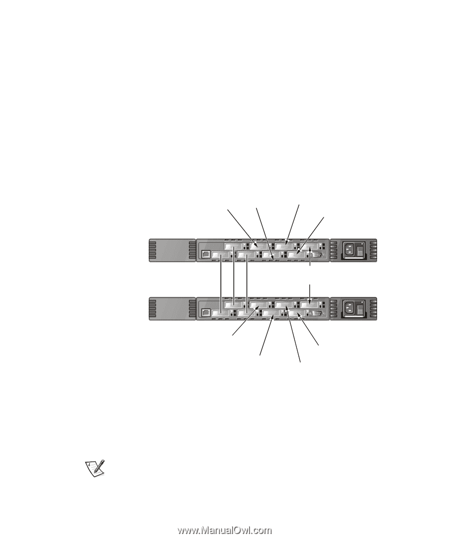
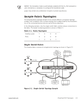
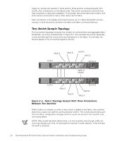
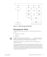
FILE LOCATION: S:\SYSTEMS\Boxer\rev_i&t\English\50UWDa00\50UWDc20.fm Figure 2-1 shows the switch's F_Ports and FL_Ports and the corresponding N_Port and NL_Port connections on the device side. The switch connections are shown as they would be in a physical installation. Functionally, the switch becomes a fabric with every device connected to every other device by the fabric. Each connection is full duplex with transmissions up to 1 Gbps bandwidth simultaneously, in both directions, between the fabric and fabric-connected devices. Two-Switch Sample Topology The two-switch topology increases the number of connectivities and aggregate fabric bandwidth, as shown schematically in Figure 2-2. The switches are shown physically connected although the connections are transparent in the fabric. Functionally, the devices appear to be connected together directly. RAID A E_Port RAID B HOST3 HOST4 Switch A JBOD A HOST5 E_Port HOST1 HOST2 Switch B RAID B RAID A Figure 2-2. Fabric Topology Sample With Three Connections Between Two Switches When a fabric is initiated, or when a new switch is added to the fabric, the switches determine a least-cost path for each destination switch. This is done dynamically each time the fabric configuration changes and the results are stored in the switch's internal routing tables. NOTE: After a path has been determined, it is not rerouted, even though traffic volume may change over time, for each path to maintain in-order delivery. If the link fails, the path is rerouted. DELL CONFIDENTIAL - Preliminary 4/6/00 2-4 Dell PowerVault 51F 8-Port Fibre Channel Switch Installation and Troubleshooting Guide
-
 1
1 -
2
-
3
-
4
-
5
-
6
-
7
-
8
-
9
-
10
-
11
-
12
-
13
-
14
-
15
-
16
-
17
-
18
-
19
-
20
-
21
-
22
-
23
-
24
-
25
-
26
-
27
-
28
-
29
-
30
-
31
-
32
-
33
-
34
-
35
-
36
-
37
-
38
-
39
-
40
-
41
-
42
-
43
-
44
-
 45
45 -
 46
46 -
 47
47 -
 48
48 -
 49
49 -
 50
50 -
 51
51 -
 52
52 -
 53
53 -
 54
54 -
 55
55 -
56
-
57
-
58
-
59
-
60
-
61
-
62
-
63
-
64
-
65
-
66
-
67
-
68
-
69
-
70
-
71
-
72
-
73
-
74
-
75
-
76
-
77
-
78
-
79
-
80
-
81
-
82
-
83
-
84
-
85
-
86
-
87
-
88
-
89
-
90
-
91
-
92
-
93
-
94
-
95
-
96
-
97
-
98
-
99
-
100
-
101
-
102
-
103
-
104
-
105
-
106
-
107
-
108
-
109
-
110
-
111
-
112
-
113
-
114
-
115
-
116
-
117
-
118
-
119
-
120
-
121
-
122
-
123
-
124
-
125
-
126
-
127
-
128
-
129
-
130
-
131
-
132
-
133
-
134
-
135
-
136
-
137
-
138
-
139
-
140
-
141
-
142
-
143
-
144
-
145
-
146
-
147
-
148
-
149
-
150
-
151
-
152
-
153
-
154
-
155
-
156
 |
 |