Dell Precision R5400 Remote Access Device: Networking Considerations - Page 9
Datacenter, User Network - rack
 |
View all Dell Precision R5400 manuals
Add to My Manuals
Save this manual to your list of manuals |
Page 9 highlights
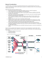
Figure 4: Example 178 User PCoIP Technology Deployment Datacenter User Network Rack Workstations Blade PC's Workgroup Switches 40x Task Workers 8x Knowledge Workers Datacenter Switches 8x Task Workers 40x Knowledge Workers 36x Knowledge Workers 5x Performance Users IP SAN/NAS Connection User Data User Profiles Manager 36x Knowledge Workers 5x Performance users 48 Task Workers 120 Knowledge Workers 10 Performance Users Blade PCs Rack Workstation Datacenter switches Workgroup Switches 1 rack with 11x blade PC chassis Each blade PC chassis supports 16 blades to support a maximum of 176 end-users 1 rack with 10 rackmount workstations for 10 Performance Users A single 24 port 10/100/1000 switch is mounted on the rack 2 redundant switches with at least 18 Gigabit Ethernet ports Each datacenter switch would use 13 ports to Blade PC and rack workstation chassis', 1 port for switch setup and failover communication, and 4 ports to User Network. More ports as required for server, internet, and other network requirements. 4 x 48 port 10/100 switches with 2 GbE uplinks each for User Network distribution Figure 4 shows a datacenter/workgroup switch environment used to support the example deployment of a PCoIP system that delivers a true PC experience over a standard enterprise network. This deployment is essentially identical to the network topology required for traditional desktop PCs. Link Sizing Links which need to be sized in the above diagram are the: • blade chassis -> datacenter switch links • rack workstations -> rack workstation switch links • rack workstation switch -> datacenter switch links • datacenter switch -> workgroup switch links • workgroup switch -> Portal links Blade chassis -> datacenter switch links The worst-case blade chassis would have 5 task workers and 11 knowledge workers allocated on it. In this example, PCoIP traffic and PC traffic are combined in the blade PC chassis switch, though most blade chassis support configurations where the PCoIP traffic can be routed through a separate link from the PC traffic. Total uplink planning bandwidth per chassis is then: ( 5 * 3 + 11 * 15 ) * 1.1 = 198 Mbps Each uplink will have a capacity of 1 Gbps which leaves 802 Mbps for PC traffic. TER0806005 Issue 1 9
-
 1
1 -
2
-
3
-
 4
4 -
 5
5 -
 6
6 -
 7
7 -
 8
8 -
 9
9 -
 10
10 -
 11
11 -
 12
12 -
 13
13
 |
 |
