Denon AVR-1712 Owners Manual - Page 94
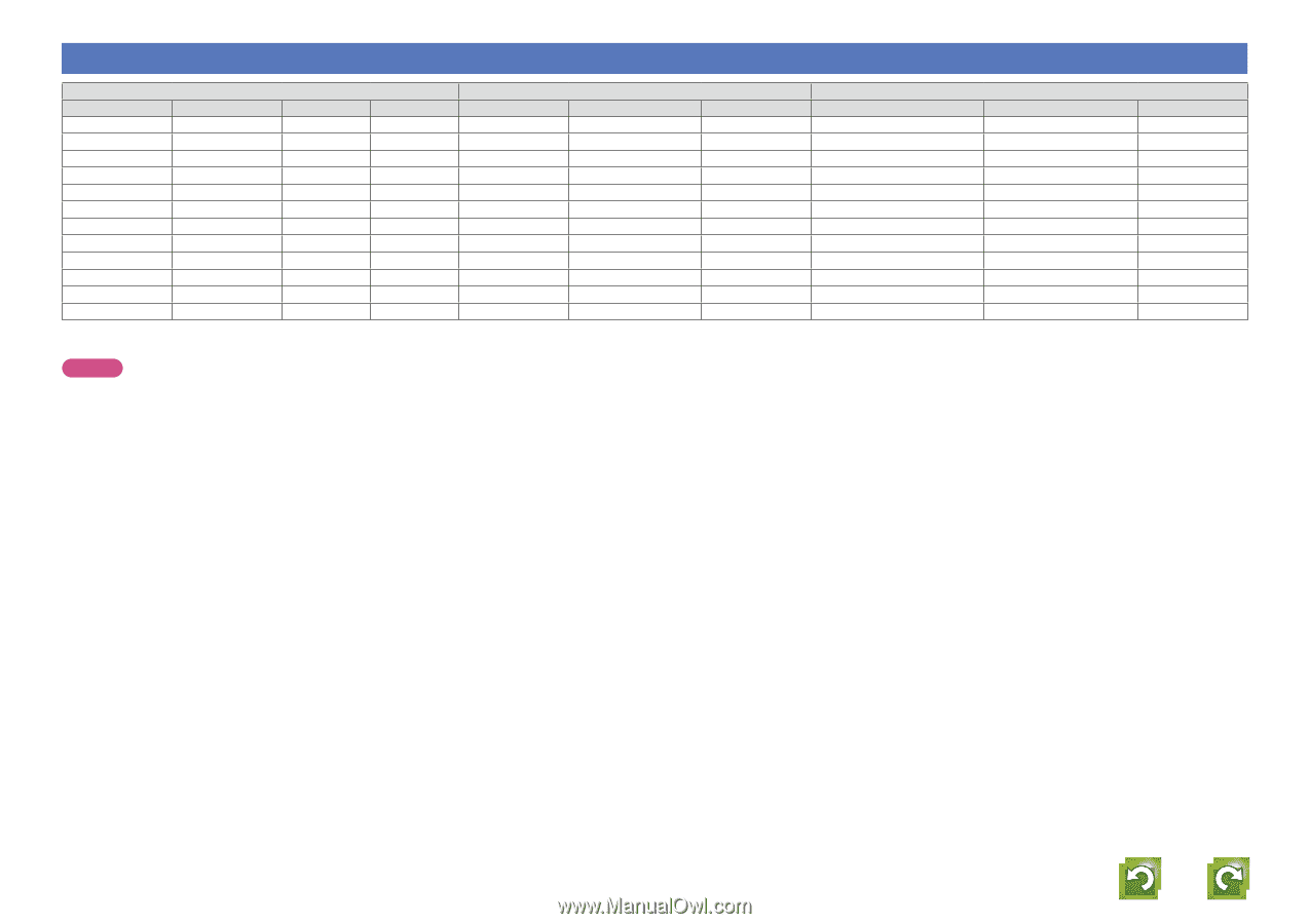
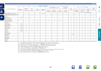
Relationship between video signals and monitor output
 |
View all Denon AVR-1712 manuals
Add to My Manuals
Save this manual to your list of manuals |
Page 94 highlights
Basic version Relationship between video signals and monitor output Input connector HDMI COMPONENT S-VIDEO A A A A A A A A S A S A A S A A S S S A A S A A S A S S S A S S A S S S S Video signal input present A No video signal input VIDEO A S A A S A A S A A S A Output connector HDMI COMPONENT VIDEO A A A A A S A A S A S A A S S A S S S S A A A S A S S S S A S S S S S S S < > The input signal between the < > marks is output. A No video signal output Menu displayed HDMI COMPONENT Only the menu is displayed A Only the menu is displayed A Only the menu is displayed Only the menu is displayed A A (COMPONENT) Only the menu is displayed A (COMPONENT) Only the menu is displayed S (HDMI) S (HDMI) S (HDMI) A (COMPONENT) A A A S (HDMI) A (COMPONENT) S (HDMI) S (HDMI) A (COMPONENT) A (COMPONENT) S ( ) Superimposed on the picture indicated in ( ). A ( ) Only the picture in ( ) is output. VIDEO A A (VIDEO) A (S-VIDEO) A A (VIDEO) A (S-VIDEO) A A (VIDEO) A (S-VIDEO) A A (VIDEO) A (S-VIDEO) NOTE • If you operate the menu while playing back 3D video content or computer's resolution (e.g. VGA), the playback video is replaced by the menu screen. The playback video is not displayed behind the menu screen. • This unit does not show the status display while playing back 3D video content or computer's resolution (e.g. VGA). Advanced version Information 91
-
 1
1 -
2
-
3
-
4
-
5
-
6
-
7
-
8
-
9
-
10
-
11
-
12
-
13
-
14
-
15
-
16
-
17
-
18
-
19
-
20
-
21
-
22
-
23
-
24
-
25
-
26
-
27
-
28
-
29
-
30
-
31
-
32
-
33
-
34
-
35
-
36
-
37
-
38
-
39
-
40
-
41
-
42
-
43
-
44
-
45
-
46
-
47
-
48
-
49
-
50
-
51
-
52
-
53
-
54
-
55
-
56
-
57
-
58
-
59
-
60
-
61
-
62
-
63
-
64
-
65
-
66
-
67
-
68
-
69
-
70
-
71
-
72
-
73
-
74
-
75
-
76
-
77
-
78
-
79
-
80
-
81
-
82
-
83
-
84
-
85
-
86
-
87
-
88
-
 89
89 -
 90
90 -
 91
91 -
 92
92 -
 93
93 -
 94
94 -
 95
95 -
 96
96 -
 97
97 -
 98
98 -
 99
99 -
100
-
101
-
102
-
103
-
104
 |
 |