Denon DRA-697CI Owners Manual - English - Page 8
Connections
 |
UPC - 081757507332
View all Denon DRA-697CI manuals
Add to My Manuals
Save this manual to your list of manuals |
Page 8 highlights
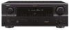
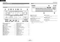
ENGLISH Getting Started ZONE3 ON/OFF buttons 20) ZONE2 ON/OFF buttons 20) Number buttons (0 ~ 9, +10 14, 16, 22) BAND button 14) Memory block buttons (A ~ G 14) Function buttons 12) MAIN ZONE ON/OFF buttons 20) [ Rear ] ¢ ZONE remote control unit (RC-1056) ZONE select switch 20) [ Front ] Function buttons 20) Number buttons (0 ~ 9 14, 16) SEARCH button 16) Memory block buttons (A ~ G 14) NOTE: • If buttons on the front or rear are pressed strongly, the button on the opposite side will be activated too. MODE button 14, 18) MEMORY button 14) TUNING buttons 14) Connections Cable indications The hookup diagrams on the subsequent pages assume the use of the following optional connection cables (not supplied). Audio cable Video cable A Analog connections (Stereo) D Video connections (White) (Red) L L R R Pin-plug cable (Yellow) Video cable (75 Ω/ohms video pin-plug cable) B Analog connections (Monaural, for subwoofer) Signal direction Audio signal Pin-plug cable C Speaker connections IN OUT OUT IN Video signal ZONE ON/OFF buttons 20) Speaker cable IN OUT OUT IN NOTE: • Do not plug in the power supply cord until all connections have been completed. • When making connections, also refer to the operating instructions of the other components. • Be sure to connect the left and right channels properly (left with left, right with right). • Do not bundle power cords together with speaker cables. Doing so could result in humming or noise. Volume control buttons 20) BAND button 14) 5 ENGLISH
-
 1
1 -
2
-
 3
3 -
 4
4 -
 5
5 -
 6
6 -
 7
7 -
 8
8 -
 9
9 -
 10
10 -
 11
11 -
 12
12 -
 13
13 -
14
-
15
-
16
-
17
-
18
-
19
-
20
-
21
-
22
-
23
-
24
-
25
-
26
-
27
-
28
-
29
-
30
-
31
-
32
-
33
-
34
 |
 |
